Designing a Quantum-RF Circuit
Explore a quantum-RF PDK component, simulate it, and create a circuit with a transmon and a resonator by drawing the schematic, reviewing the layout, and connecting components together.
Before you get started, create a new sample project and select the quantum-rf-public-main sample project.
Explore and simulate a resonator
-
In the Visual Studio Code sidebar, select the
GF+ tab. Click theCreate Schematicbutton and typequarter_wr_simulationfor the name, then pressEnter.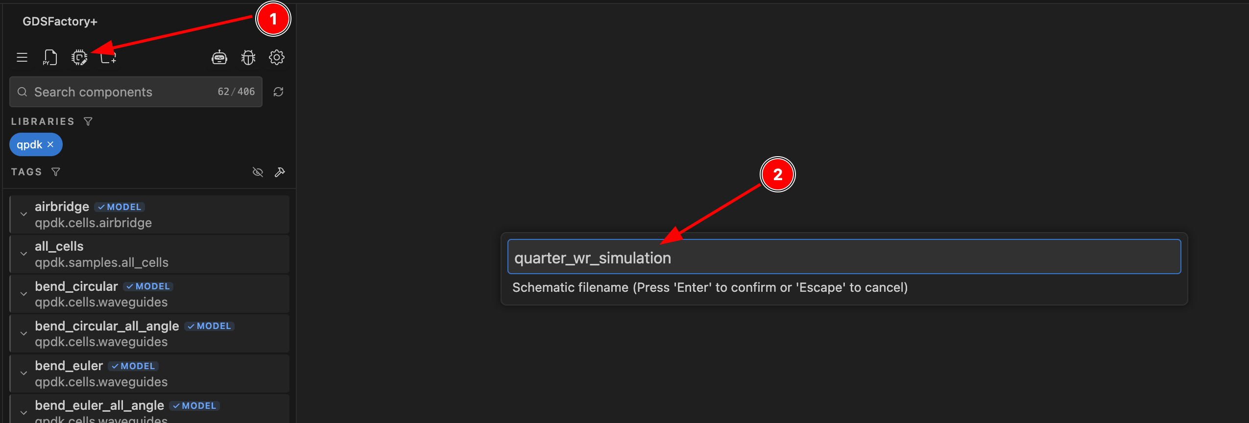
-
In the
Schematic View, click theAdd Componenttool (or click it in the bottom toolbar), then search forquarter_wave_resonator_coupledfrom the qpdk library and select the desired component.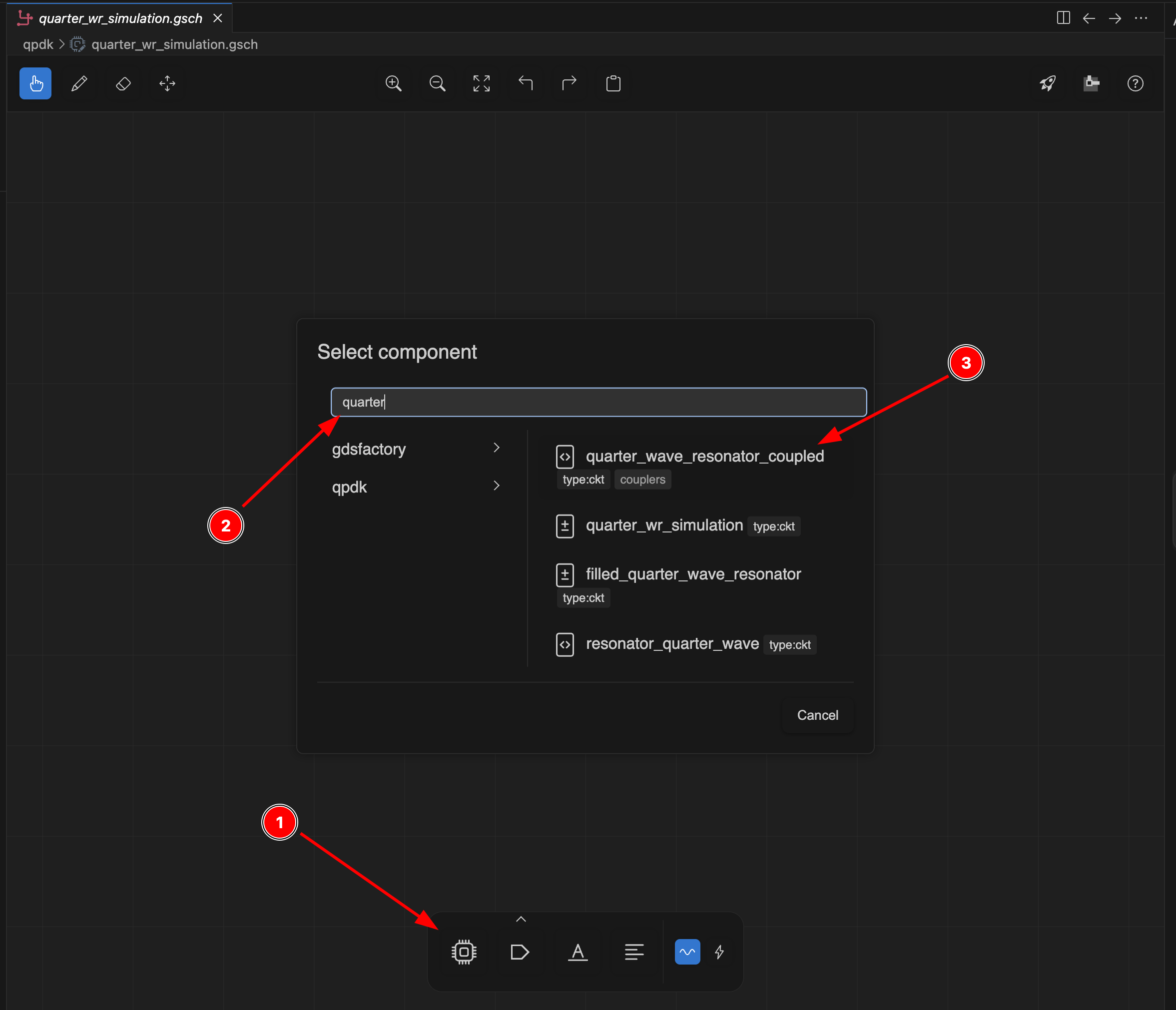
-
In this view, you can see the ports of the component
coupling_o1(P1) and the outputcoupling_o2p(P2). Before running a simulation, we have to select the ports that we want to use. Click thePortbutton in the bottom bar and then click on thecoupling_o1andcoupling_o2ports. The rotation of the port can be changed with the keyR. Then click theSimulatebutton in the top-right corner to run a simulation.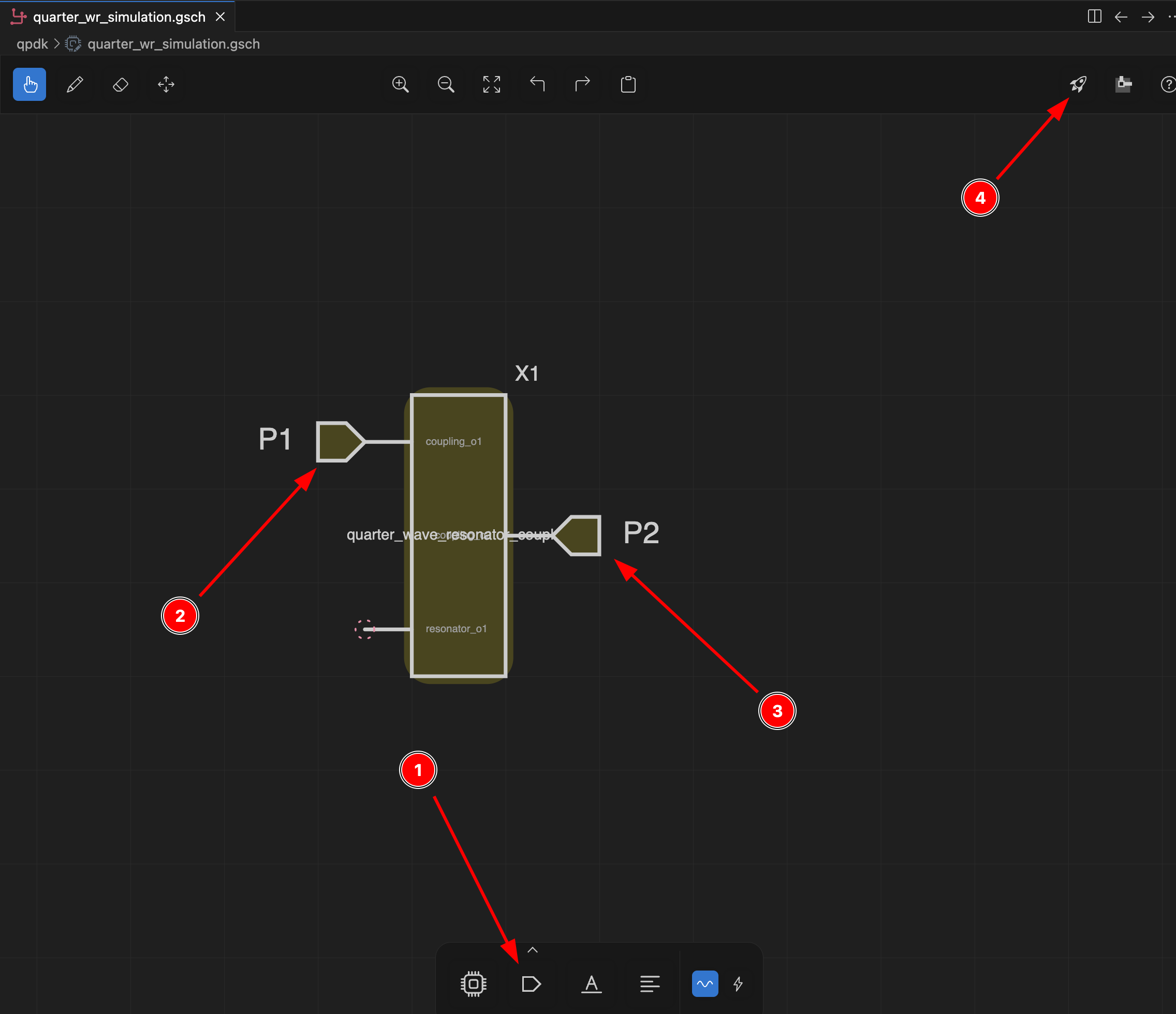
-
The simulation panel opens with SAX S-parameter results. Click
Simulateto run. You can toggle additional S-parameter combinations on or off (P1 ↔ P1, P2 ↔ P1, P2 ↔ P2).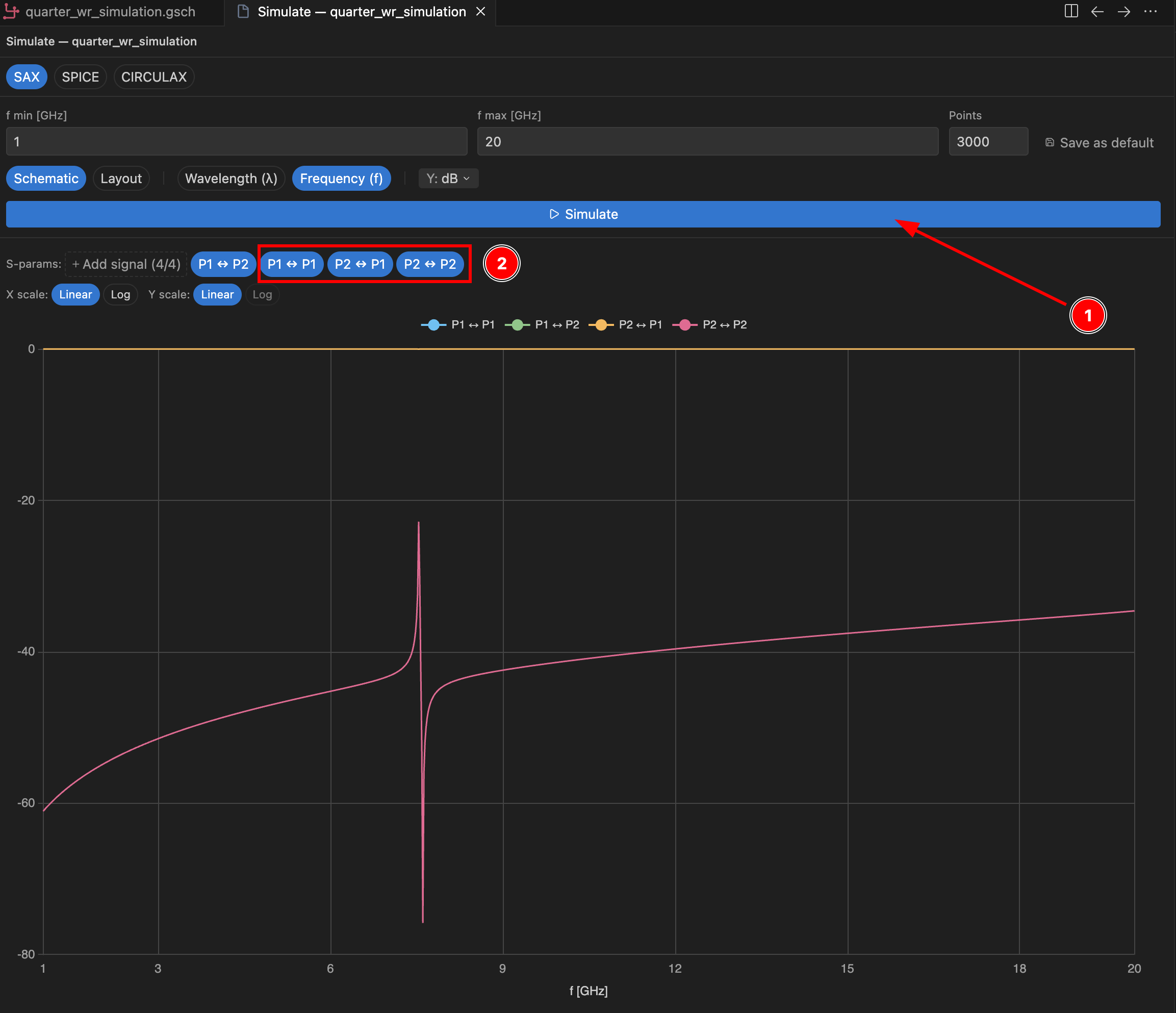
-
With only
P1 ↔ P2selected, you can zoom in to see the resonance at ~7.537 GHz.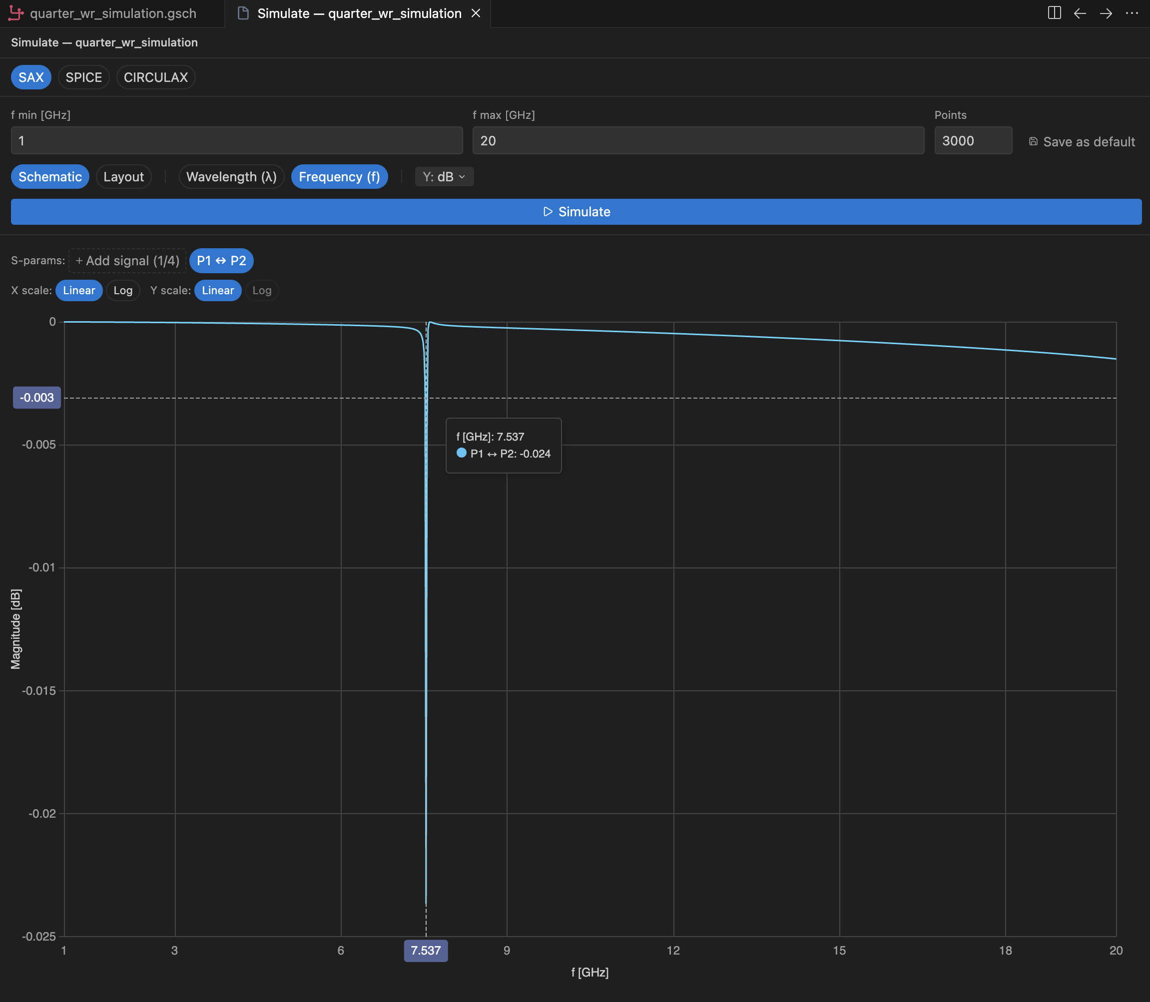
Create the transmon circuit schematic
-
Go back to the
GF+ taband create a new schematic. Name ittransmon_with_resonator_2, then pressEnter.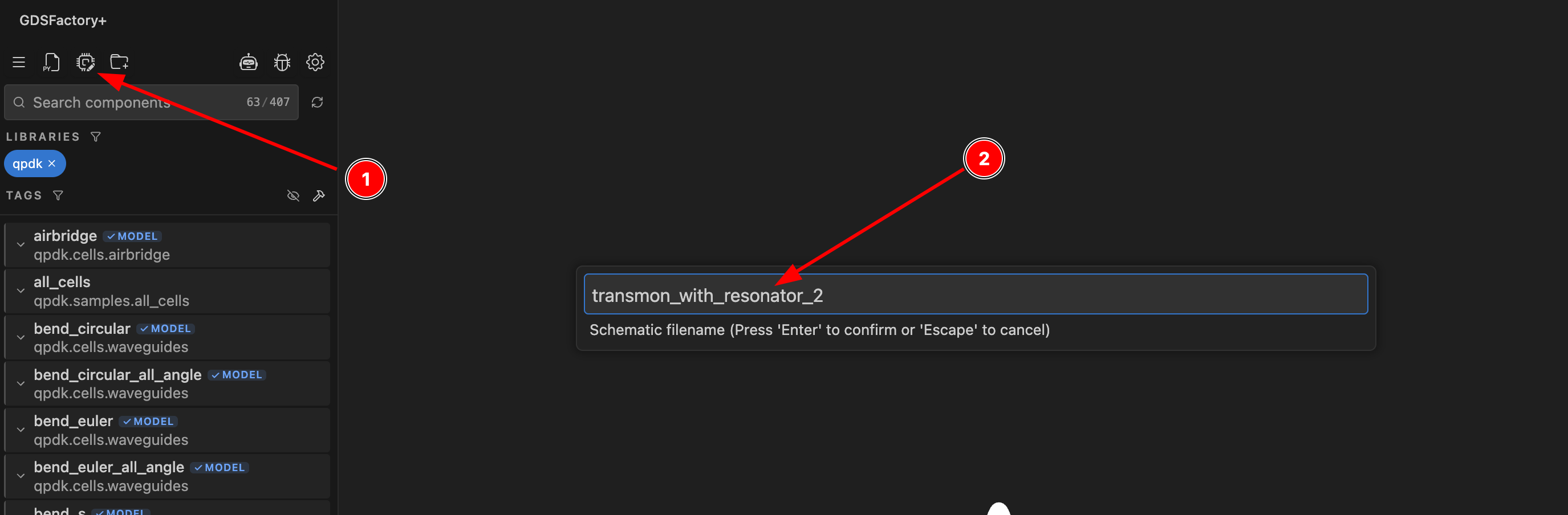
-
Using the
Add Componenttool, add the following components:double_pad_transmon_with_bboxresonatorplate_capacitor_single
Right-click on the
plate_capacitor_singleinstance to see its parameters and edit its values: set the length to250and the width to80.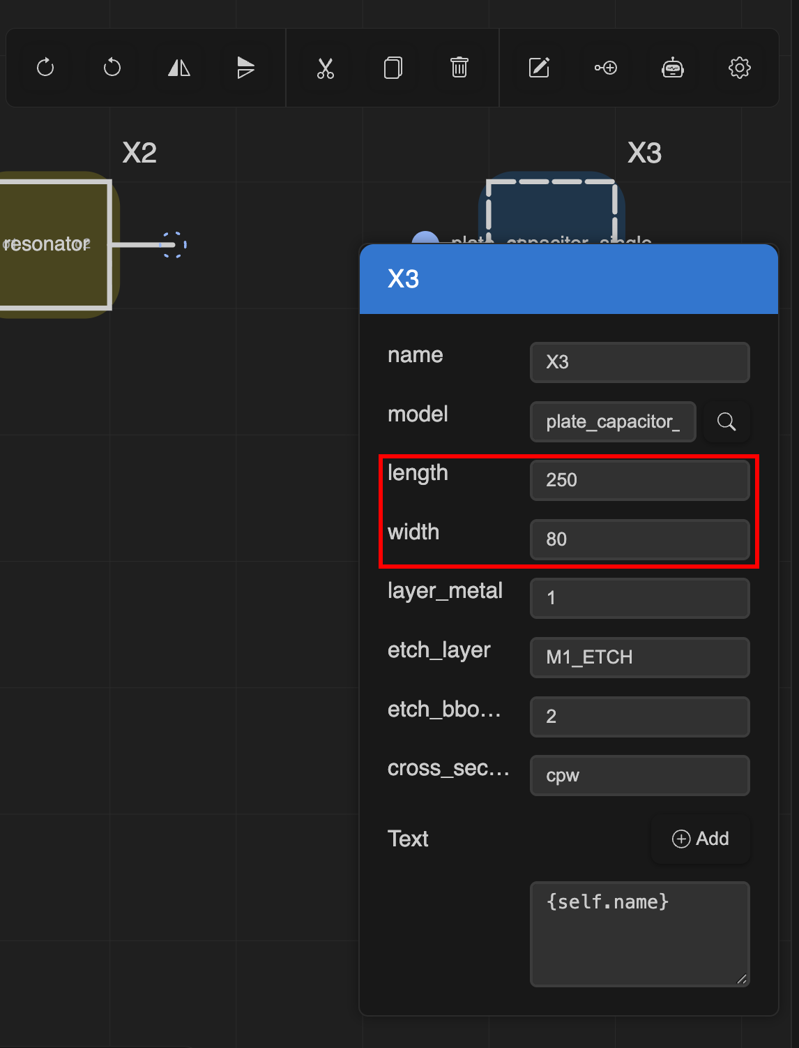
-
Once all components are placed, click
Open in Livewirein the top-right corner to open the layout editor.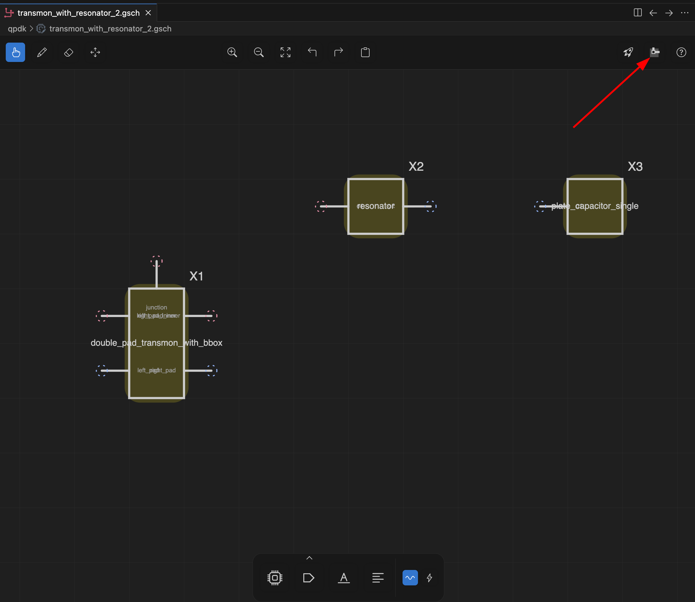
Arrange and connect components
-
In the
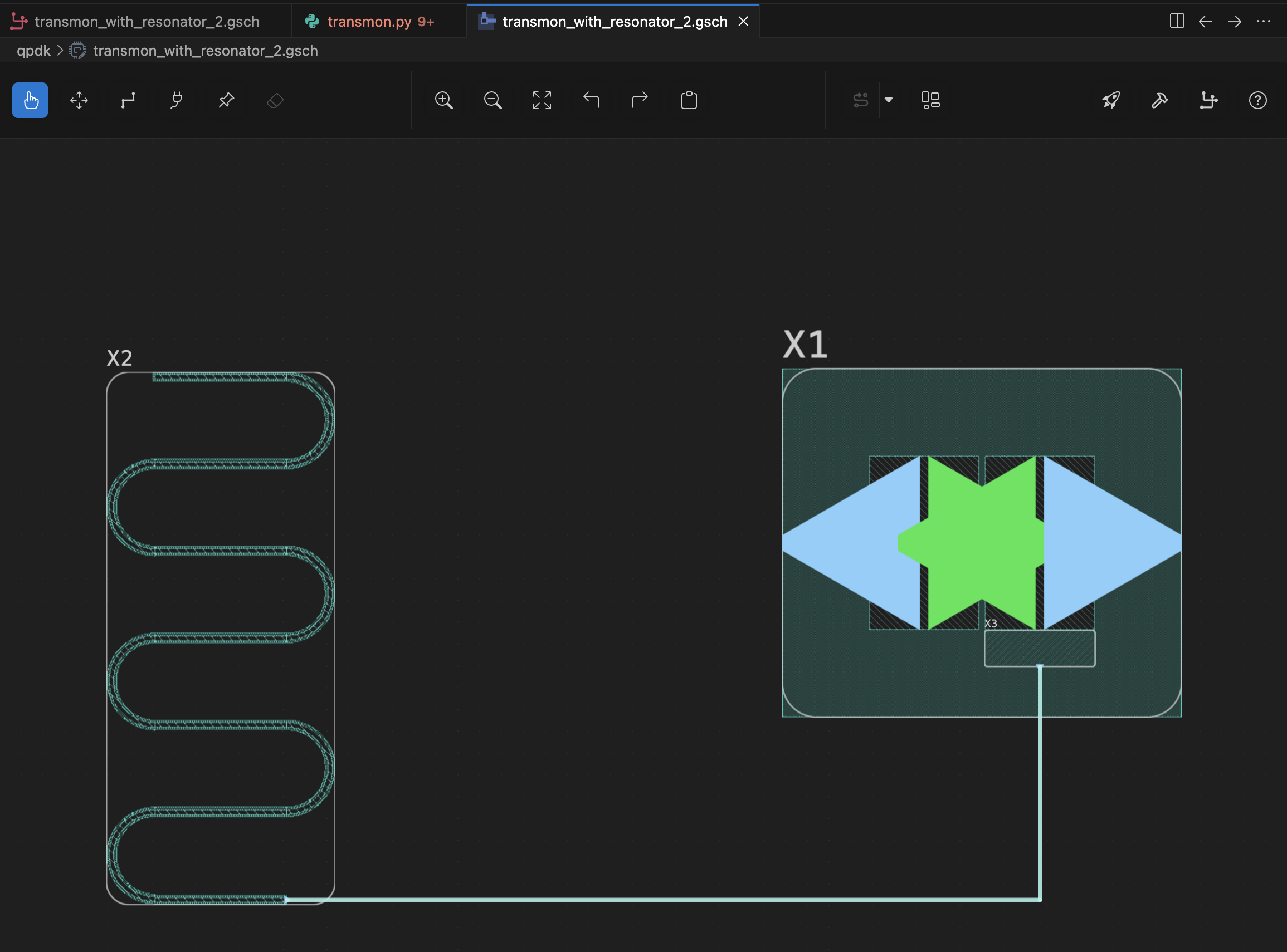
Layout View, use the select tool to rearrange the components. Position the resonator (X2) on the left and the transmon (X1) on the right, with the plate capacitor (X3) nested inside the transmon.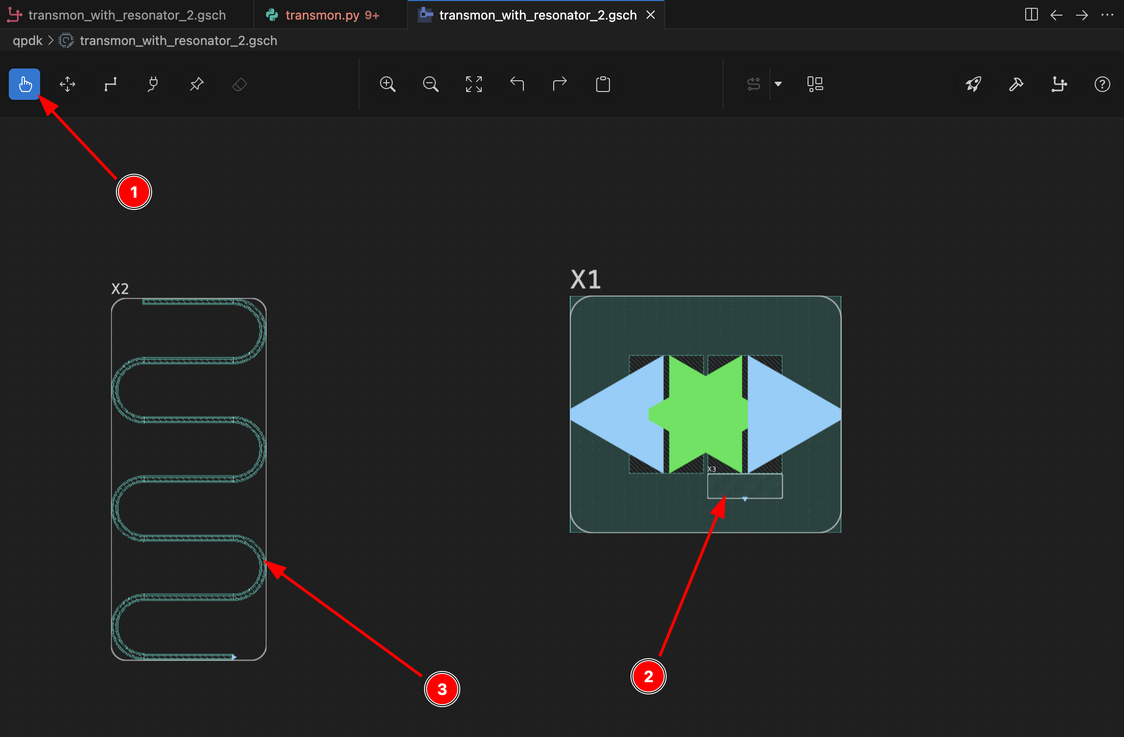
-
Select the
Route(w) tool in the layout toolbar, then draw a Manhattan route between the resonator and the transmon pad. First click on the initial port, and then click on the desired waypoints.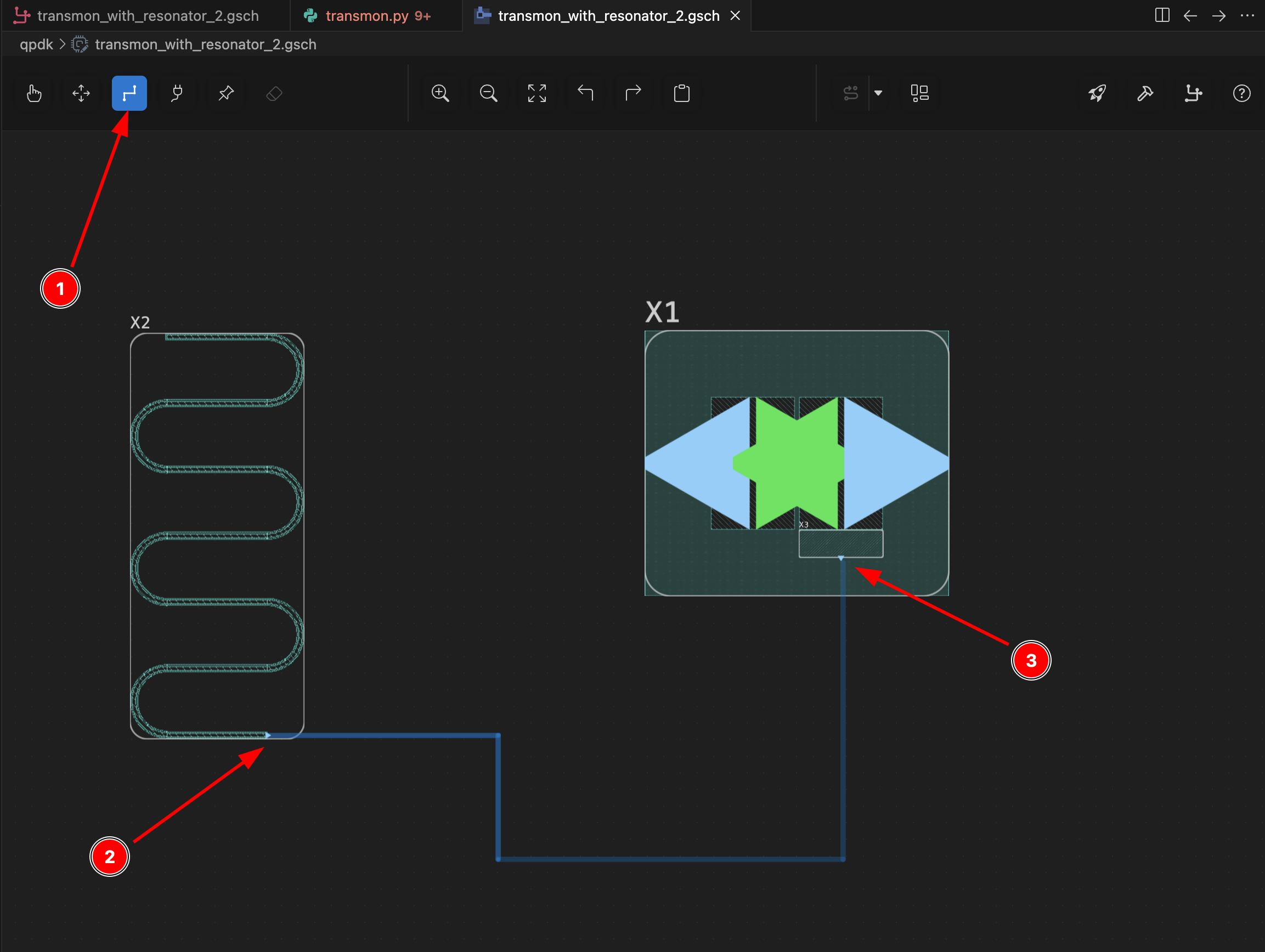
-
A good practice is to define the intended connections in the schematic first. Switch to the
Schematic Viewand select theWiretool. Draw connections between the resonator and the plate capacitor to define the circuit netlist.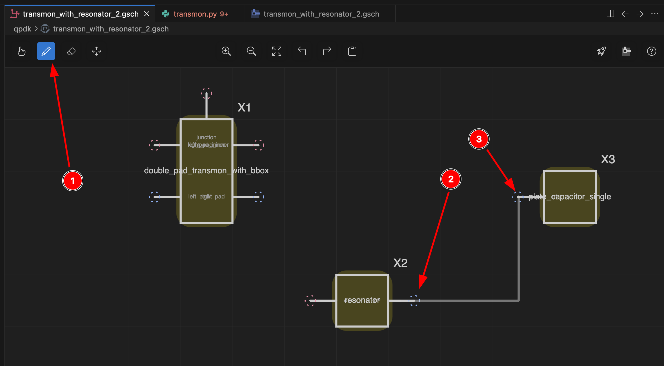
-
Back in the
Layout View, connections that exist in the schematic but are missing in the layout are shown as red double-arrow lines. Hover over one to see the tooltip — you can then right-click to auto-route with Playdough or click theAuto-routebutton.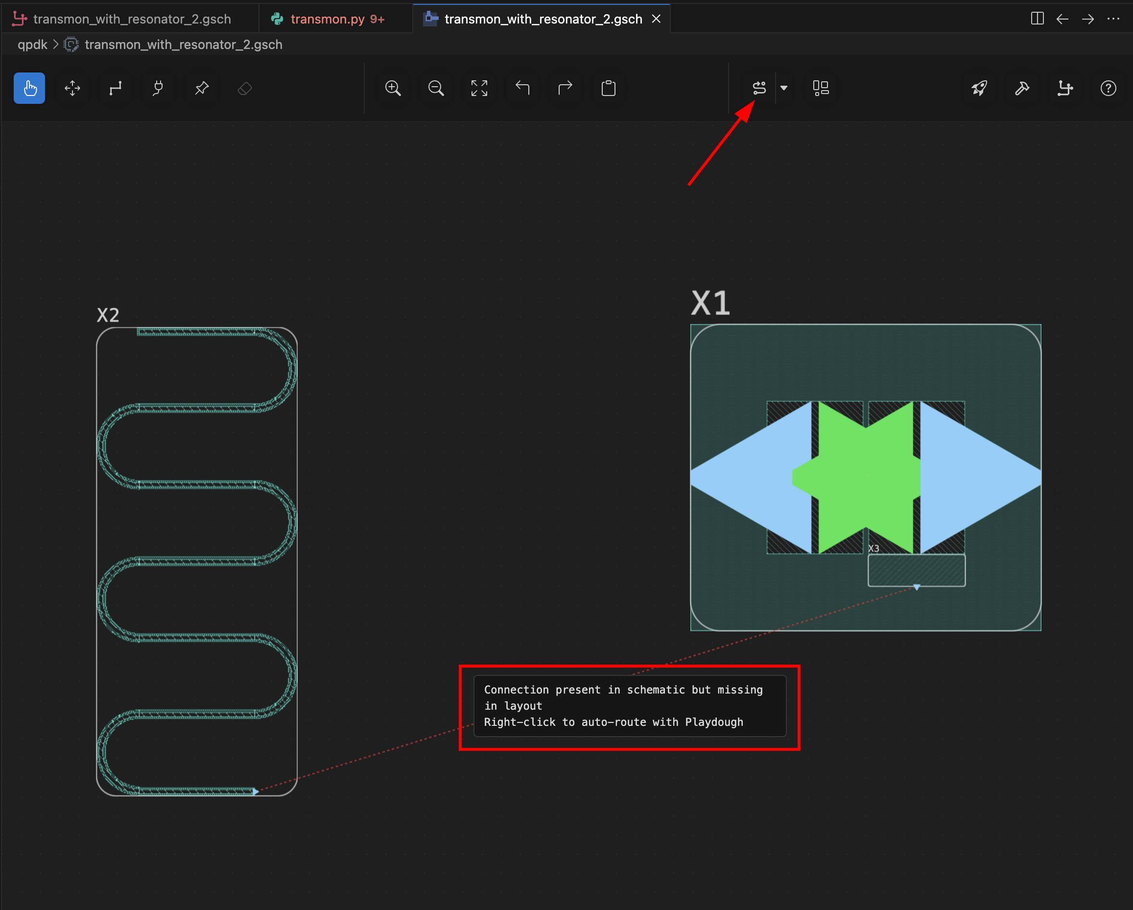
-
After auto-routing, the resonator and transmon are fully connected.