The GDSFactory+ Code Workflow
GDSFactory+ is built on top of the GDSFactory open-source Python library. GDSFactory allows you to design chips, PCBs, and other objects entirely with Python code.
This has several advantages over a graphical workflow:
- Precise layout is easier to control with code, as component placements can always be accurately referenced and relationships between components can be easily encoded.
- Laying out multiple components in a pattern is also easier with a code-based approach via the power of standard programming control-flow mechanisms like
forloops andifstatements. - Code makes it possible to define arbitrary geometry for each layer of a chip, giving more freedom than is afforded by connecting existing component schematics.
Creating a Parametric Cell
Let's create and customize a cell with Python code, and see its changes in the graphical GDS viewer. We'll start with a hard-coded cell, and then add parameters to make it a parametric cell.
-
In the Visual Studio Code sidebar, select the
GF+ tab. This will open a menu with the project components at the top (Project) and the PDK components at the bottom (Base PDK). The Process Design Kit (PDK) includes a set of predefined components provided by the foundry. In this example, we are using the UK-based foundry Cornerstone, which offers an open-source PDK.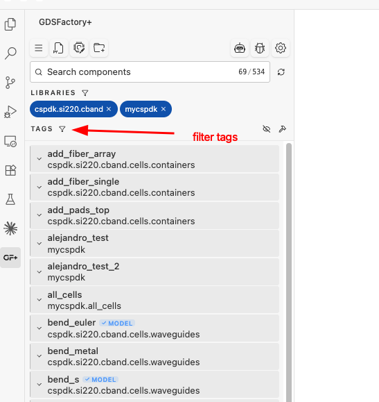
-
In the top section of the app, click the button that has a file icon with a 'py' sign on it. Then type
hellofor the name and pressenter. This will create a Python file namedhello, and open itsCode Viewin a new tab.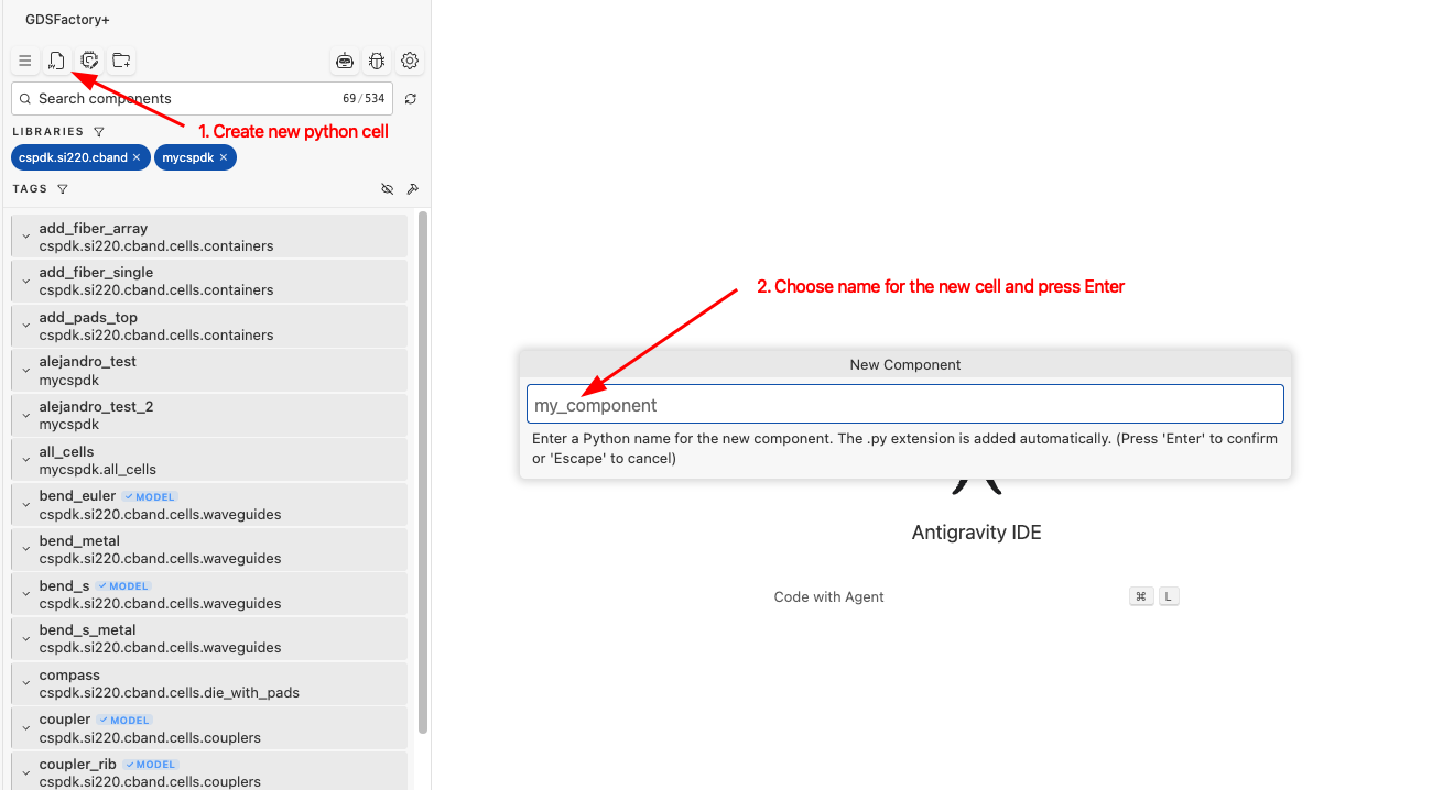
-
Replace the starter code imports with the following code:
import gdsfactory as gf @gf.cell def sample_pcell() -> gf.Component: c = gf.Component() ref1 = c.add_ref(gf.components.rectangle(size=(10, 10), layer=(1, 0))) ref2 = c.add_ref(gf.components.text("Hello", size=10, layer=(2, 0))) ref3 = c.add_ref(gf.components.text("world", size=10, layer=(2, 0))) ref1.xmax = ref2.xmin - 5 ref3.xmin = ref2.xmax + 2 ref3.rotate(90) return c -
In the right top bar of the tab, click the eye button. Then click
Show GDSto open theGDS View.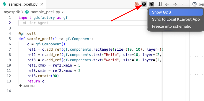
You should see something like the following image, where the Code View of the Python cell is on the left, and the GDS View (CAD file view) is on the right.
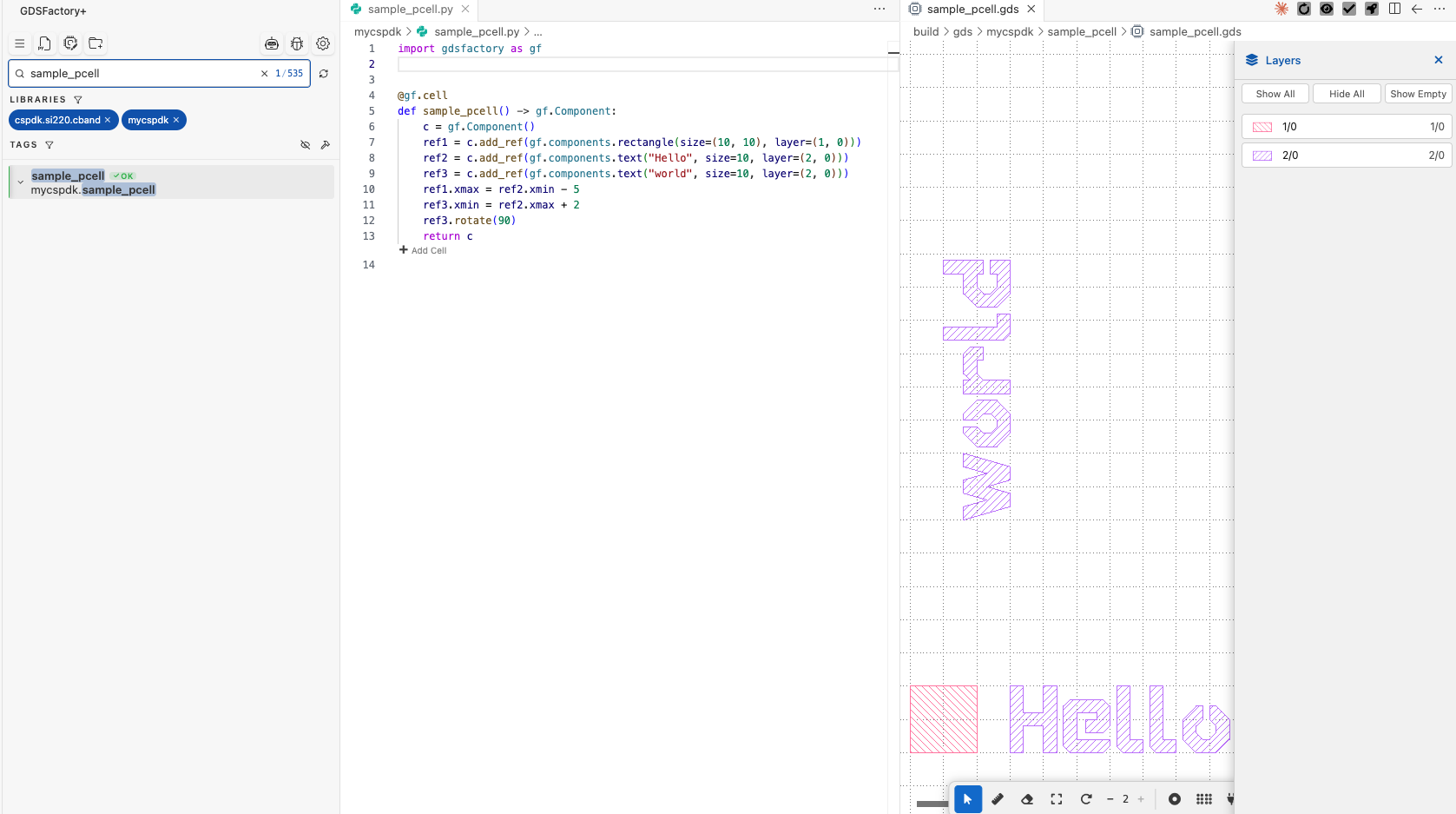
In the Code View, replace
worldwith your name to personalize your Python cell, and observe the changes in the GDS View.
Make it parametric
The previous example used a fixed cell (with no input parameters). Now, let's define a parametric cell where you can modify input parameters dynamically. For instance, we can customize the text name and size by modifying the code as shown below:
@gf.cell
def sample_pcell(size=20, name="world") -> gf.Component:
    c = gf.Component()
    ref1 = c.add_ref(gf.components.rectangle(size=(10, 10), layer=(1, 0)))
    ref2 = c.add_ref(gf.components.text("Hello", size=size, layer=(2, 0)))
    ref3 = c.add_ref(gf.components.text(name, size=size, layer=(2, 0)))
    ref1.xmax = ref2.xmin - 5
    ref3.xmin = ref2.xmax + 2
    ref3.rotate(90)
    return c
Experiment by changing the name and size parameters to see how they affect the output. 🚀
Bonus: Use the AI Agent
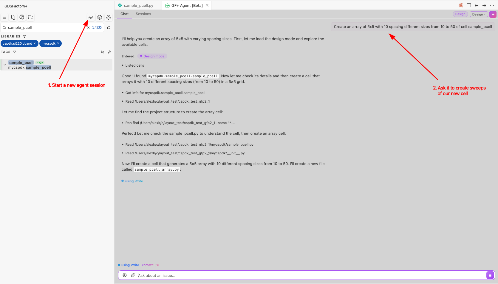
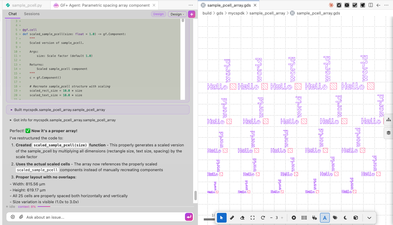
You can ask the agent to create an array of texts of different sizes; it will take care of it for you!
Iterate until you're happy with the result:
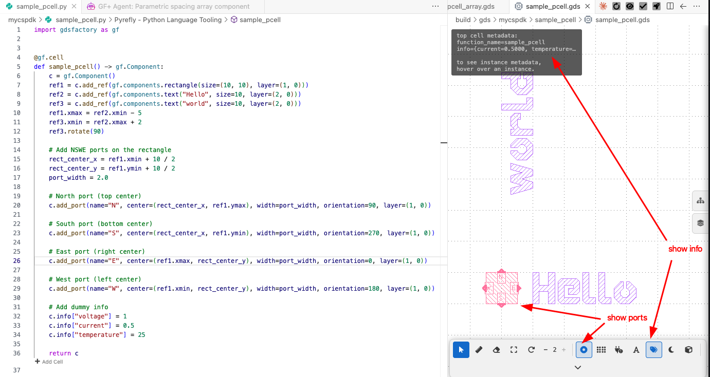
You can also ask the agent to add ports and test information:
🎉 Congratulations! You have successfully created your first custom GDSFactory cell!
For more information on designing with the GDSFactory library, see the GDSFactory docs.