Step 2: Design a Quantum-RF Circuit
In this step, we'll create a transmon with resonator circuit by drawing the schematic, review the layout, and connect components together.
Before you get started, create a new sample project and select the quantum-rf-public-main sample project.
Explore the PDK
-
In the Visual Studio Code sidebar, select the
GF+ tab.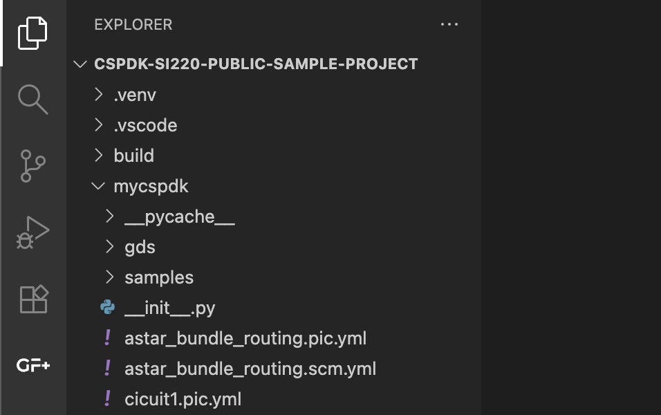
-
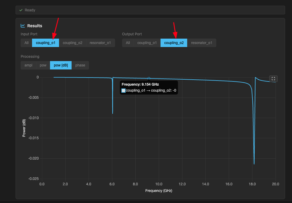
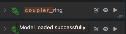
Run a simulation for the
quarter_wave_resonatorcomponent to see how it behaves.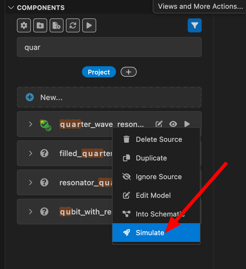
Create a schematic file
-
In the components section (Project), click on the
+and typetransmon_with_resonator_newfor the name, then pressenter. This will create a new schematic file and open itsSchematic Viewin a new tab. If you want to see the end result, you can look attransmon_with_resonator_3.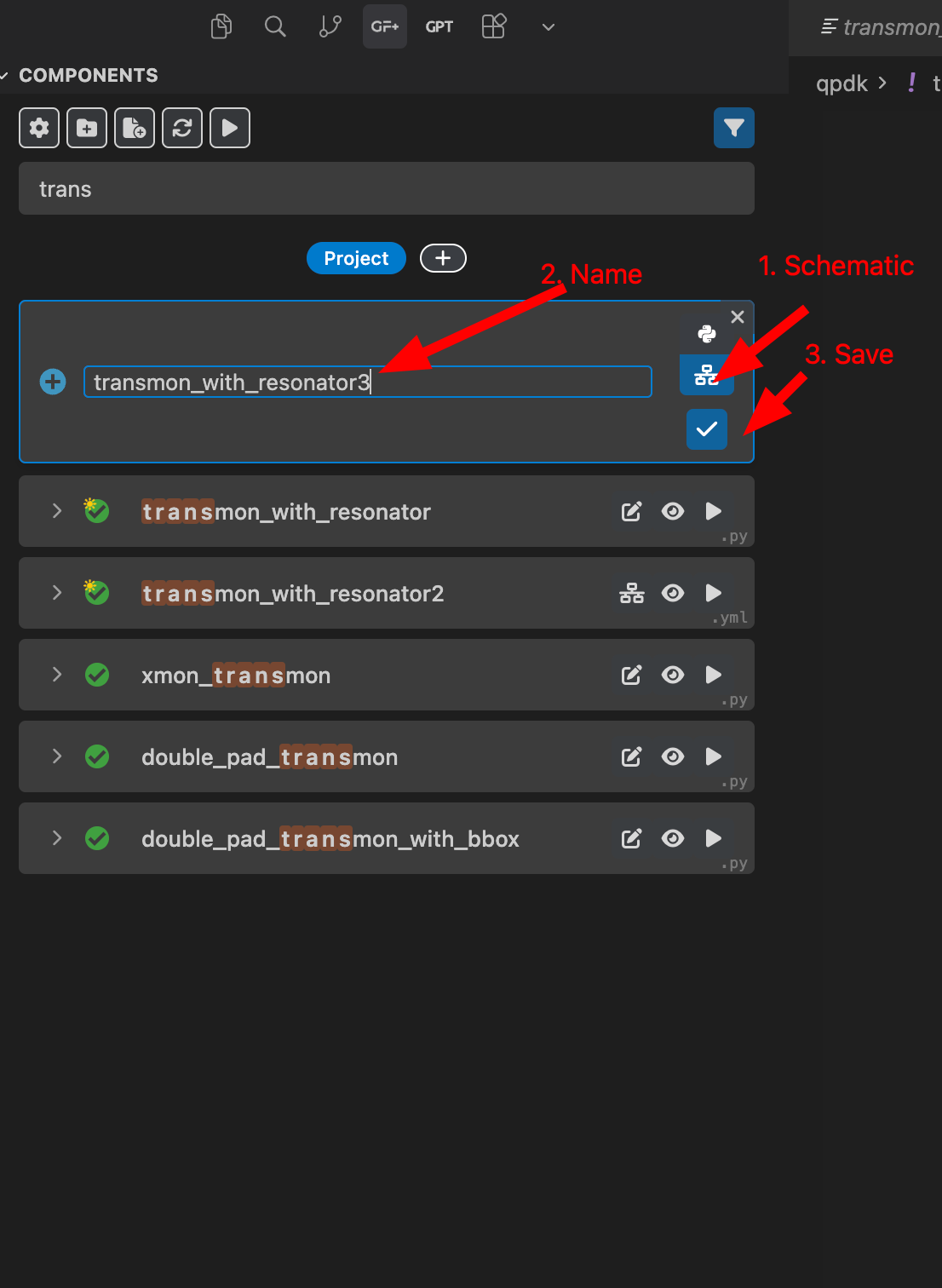
For the components in the GF+ tab, a single checkmark means that the component has only a layout, and a double checkmark means that the component has both a layout and a simulation model.
Note that some hierarchical components may not show a double checkmark, but you might still be able to simulate them if their components with models are used in the hierarchy.
Add components and connect them
-
Once in the
Schematic Viewof our new schematic file, pressito select theAdd Instancetool (or select it in the tool bar, or press+), then click anywhere in the tab to add a new instance. Add the following components: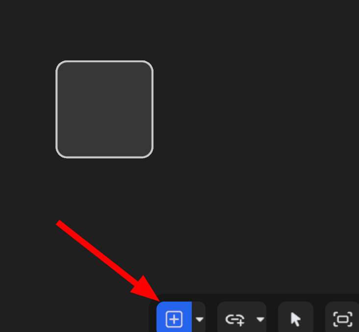 -
- double_pad_transmon_with_bbox(name itpad) -resonator-plate_capacitor_single
-
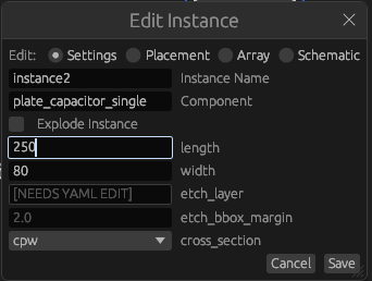
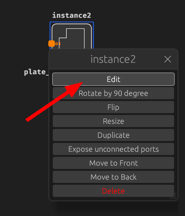
Edit the plate capacitor settings by right-clicking on it:
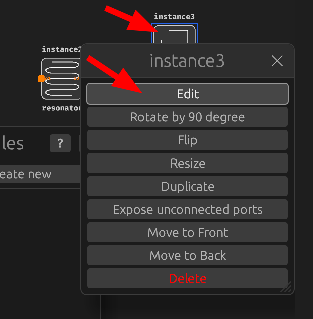
Change the length to 250 um and width to 80 um:
-
Once you added all components, press
Show GDSon the top right.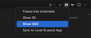
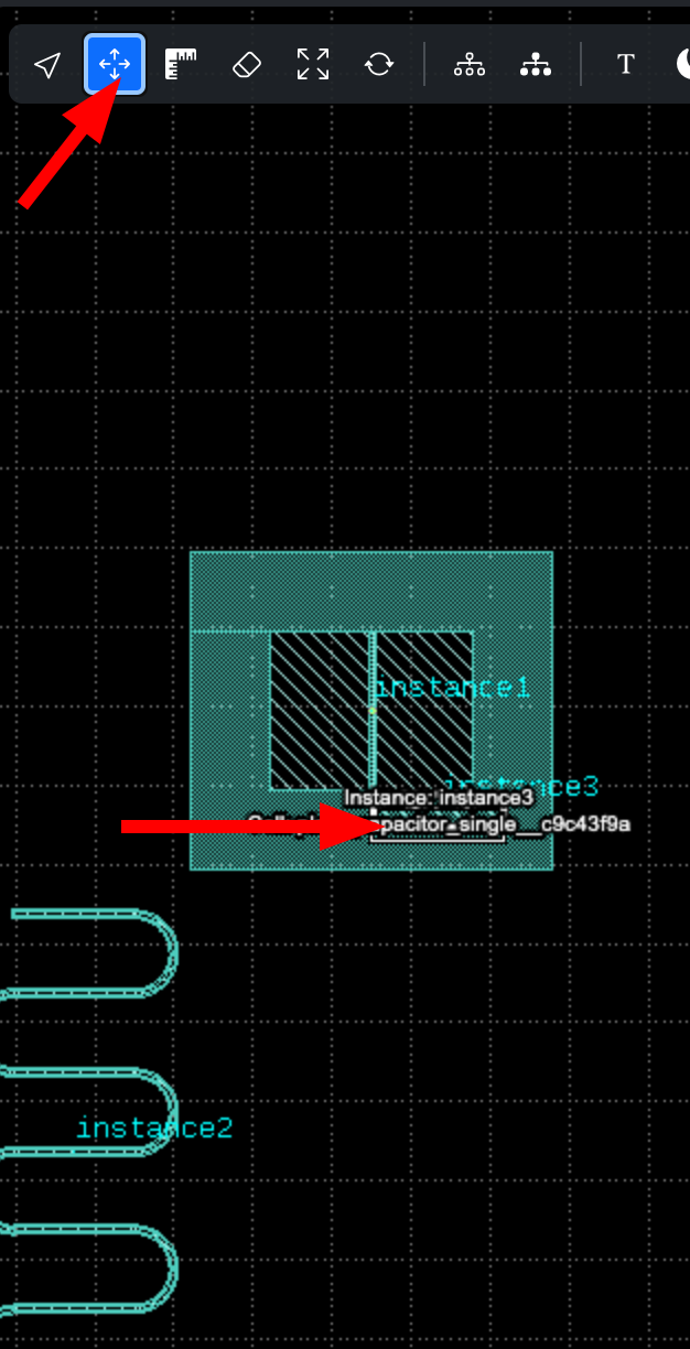
Move the plate capacitor to the right side of the pad:
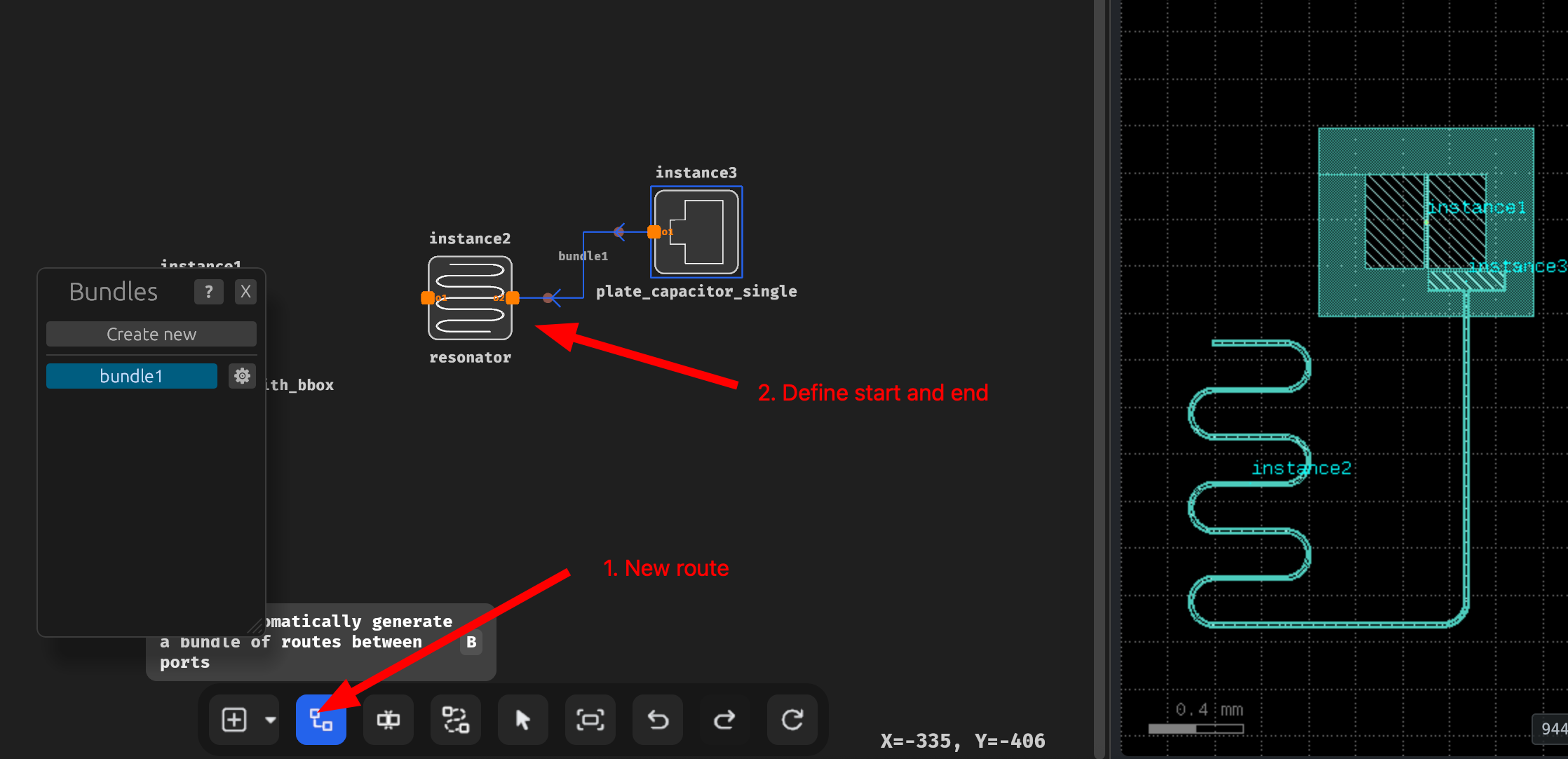
-
Click on new route and define a route from
resonatortoplate_capacitor_single: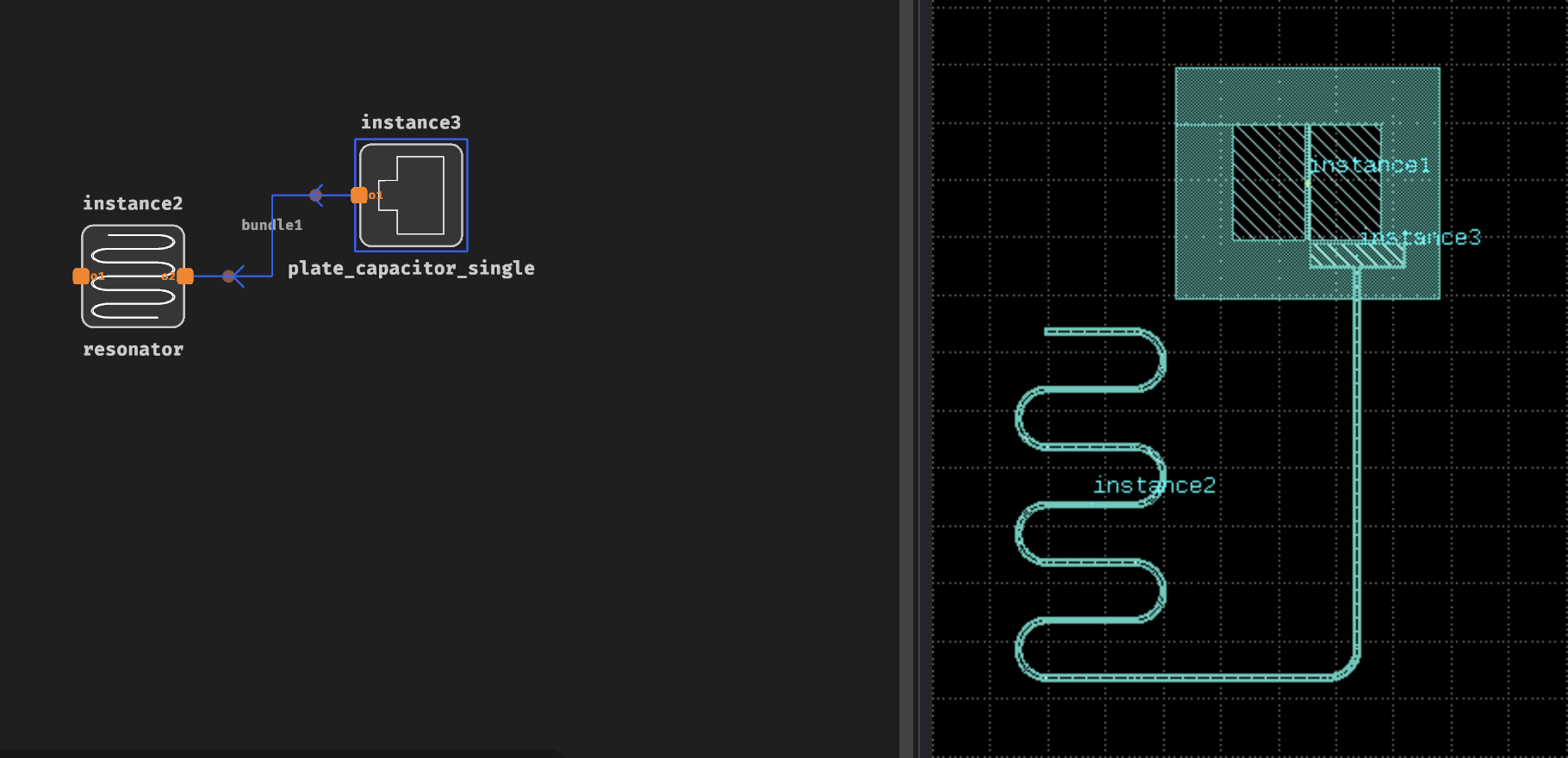
You may notice the placement and settings are not correct at first:
-
Place an auto-route between the components: