Step 3b: Check for Connectivity Errors - LVS
LVS (Layout vs. Schematic) verifies that your physical GDS layout is electrically equivalent to your .pic.yml schematic. It compares the connectivity extracted from the layout against the netlist declared in the schematic and reports any mismatches — missing connections, extra connections, wrong components, shorts, and dangling ports.
Run an LVS check
In the GDS View tab, click the checkmark dropdown (✓) in the top right toolbar and select Check LVS.
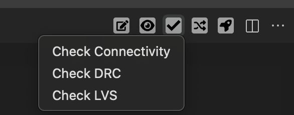
Wait for the checking process to finish. Results appear in the DRC Results sidebar under the LVS tab, showing the number of findings grouped by error category.
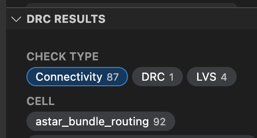
Click on any finding to zoom to the relevant geometry in the layout viewer.
Understanding LVS results
Passing LVS
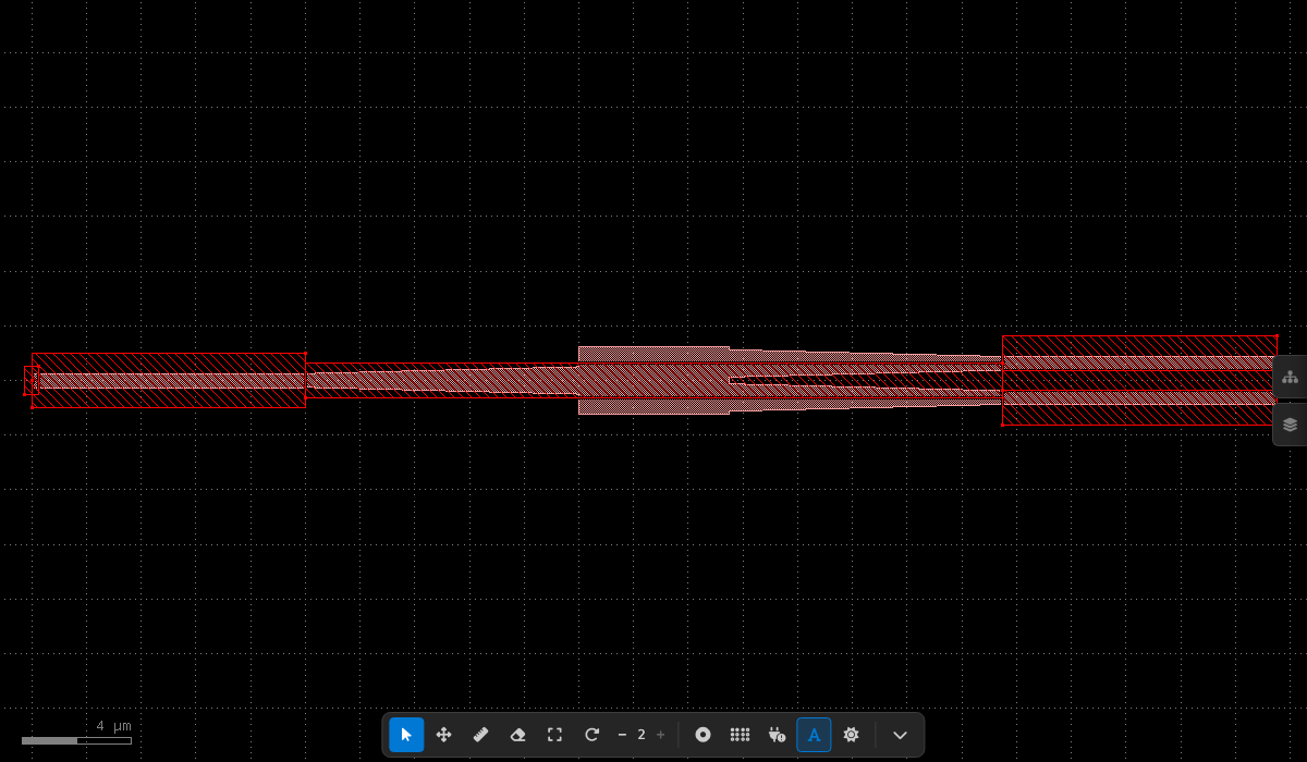
When all instances are correctly connected and match the schematic, the LVS check reports zero findings. Port markers appear white (no errors) and all instance boxes are in contact:
Failing LVS
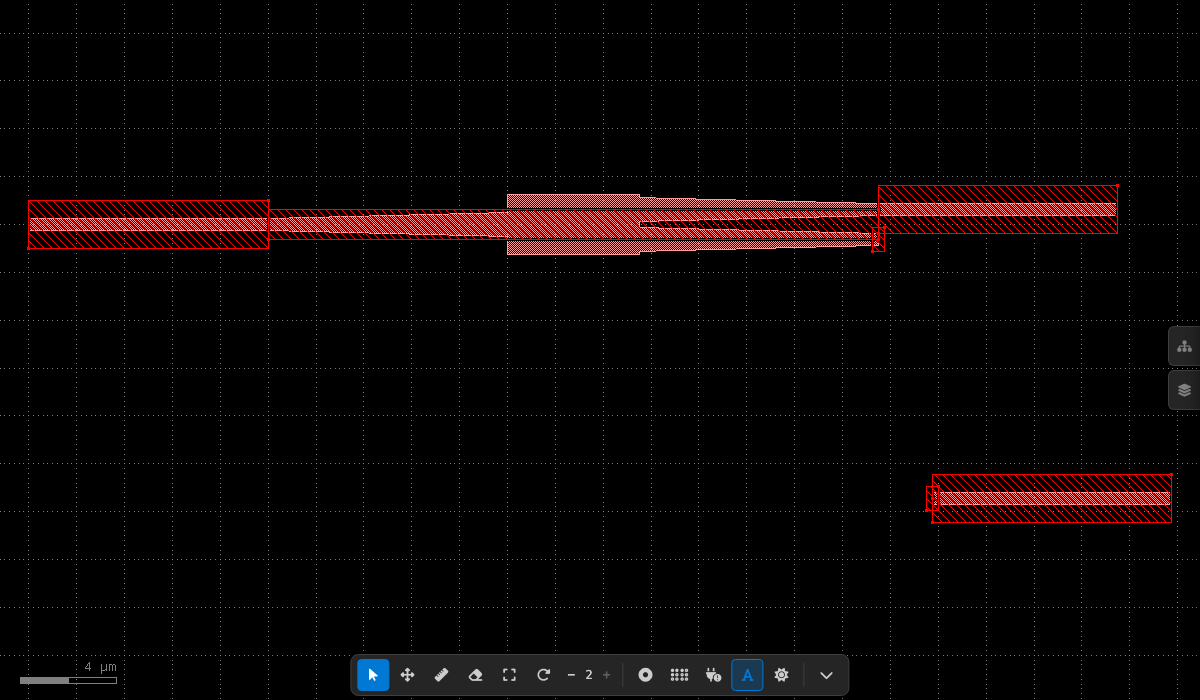
When a connection is broken — for example, an output waveguide displaced from its expected position — the affected instance appears isolated and the viewer highlights open ports and unknown nets:
Short detection
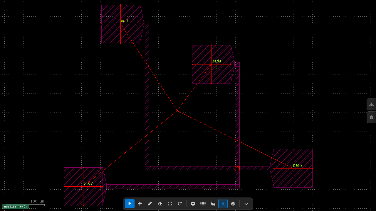
When two electrically distinct nets share a polygon on the same layer, a short is reported. Crossing markers indicate where the overlap occurs:
Open port detection
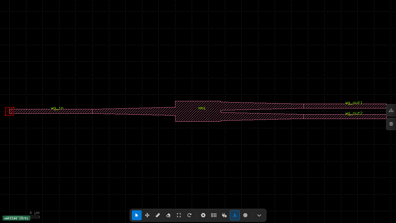
A port that exists in the layout but is not declared in the schematic's ports: block is flagged as an open. In the example below, the red box at the left marks an open port on the input waveguide:
Cross-layer short detection
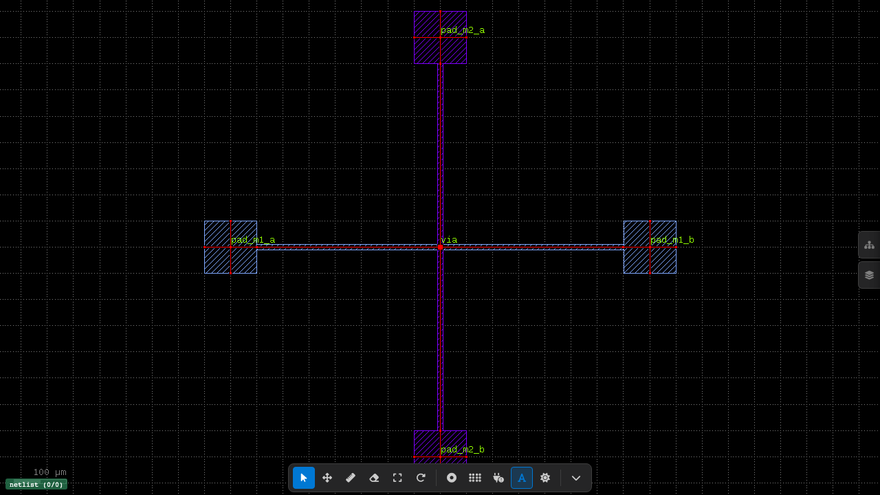
For multi-layer designs where metal layers connect through vias, LVS checks for shorts across connected layers (e.g. M1 ↔ VIA ↔ M2). In this example, M1 and M2 pads are connected through a center via — markers show where the via creates a cross-layer short between two nets that should remain independent:
Error types
Both LVS engines use the same hierarchical error categories:
| Error | Meaning |
|---|---|
LVS.instance.missing_in_layout |
Schematic instance not found in the GDS layout |
LVS.instance.missing_in_schematic |
Layout instance not in the schematic (and not routing) |
LVS.instance.component_mismatch |
Instance found but uses the wrong component type |
LVS.net.missing_in_layout |
Schematic connection not found in the layout |
LVS.net.missing_in_schematic |
Extra connection in layout not declared in schematic |
LVS.port.missing_in_layout |
Top-level schematic port absent from the layout |
LVS.port.missing_in_schematic |
Top-level layout port not in the schematic |
LVS.port.mismatch |
Port connects to a different instance port than expected |
LVS.open |
Dangling port — not connected and not a top-level port |
LVS.short |
Polygon overlap between electrically distinct nets |
Choosing an LVS engine
GDSFactory+ supports two LVS engines:
- elvis (default) — lightweight, fast engine focused on connectivity comparison
- kfactory-lvs — full-featured engine with additional integrity checks (port mismatch, instance overlap, dangling port detection)
Both engines automatically read layer connectivity and short-detection layers from the active PDK — no manual layer configuration is needed. Both produce compatible .lyrdb report files viewable in the GDS viewer.
To switch engines, add the following to your project's pyproject.toml:
Alternatively, set the GFP_LVS_ENGINE environment variable:
For programmatic access, see the Python SDK reference.
Next Steps
Continue to Step 4: Build a Component with the AI Agent.