Step 2: Design a Photonics Circuit
In this step, we'll create a Ring Filter circuit by drawing the schematic, review the layout, connect components together, and simulate the circuit.
The following video walks through the same steps. The written guide below contains the most up-to-date instructions.
Create a schematic file
-
In the Visual Studio Code sidebar, select the
GF+ tab.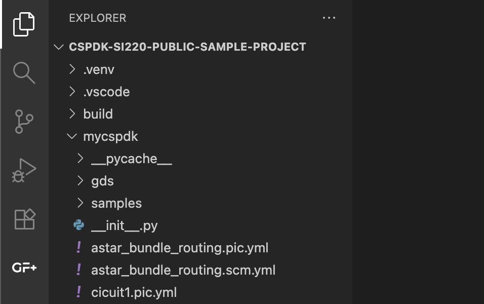
-
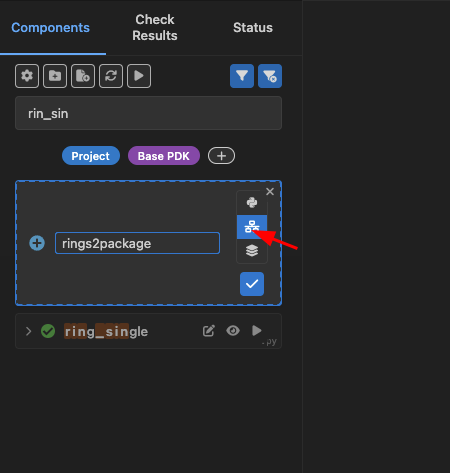
In the project components section (Project), hover over the word project, then click the button that has a file icon with a + sign. This time select
Create Schematicand typerings1for the name, then pressenter. This will create a new schematic file namedrings1and open itsSchematic Viewin a new tab.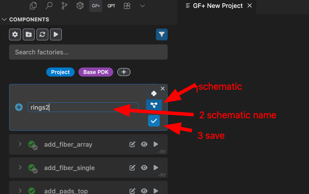
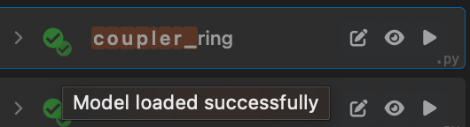
Components are built when needed. In other words, they are lazy loaded. When a component is greyed out, you can click the play button at the top of the Components menu to load it.

For the components in the GF+ tab, a single checkmark means that the component has only a layout, and a double checkmark means that the component has both a layout and a simulation model associated with it.
Note that some hierarchical components may not show a double checkmark, but you might still be able to simulate them if their components with models are used in the hierarchy.
Add components and connect them
-
Once in the
Schematic Viewof our new schematic file, pressito select theAdd Instancetool (or select it in the tool bar, or press+), then click anywhere in the tab to add a new instance. In the pop-up menu, selectring_singleas the component and typer1as the name.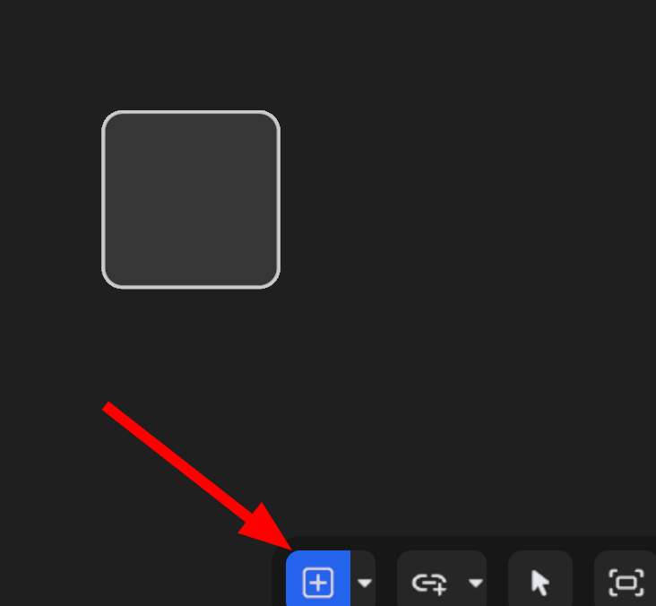
-
Repeat the process to create a second ring, and name it
r2. Then pressShow GDSon the top right.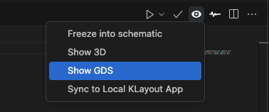
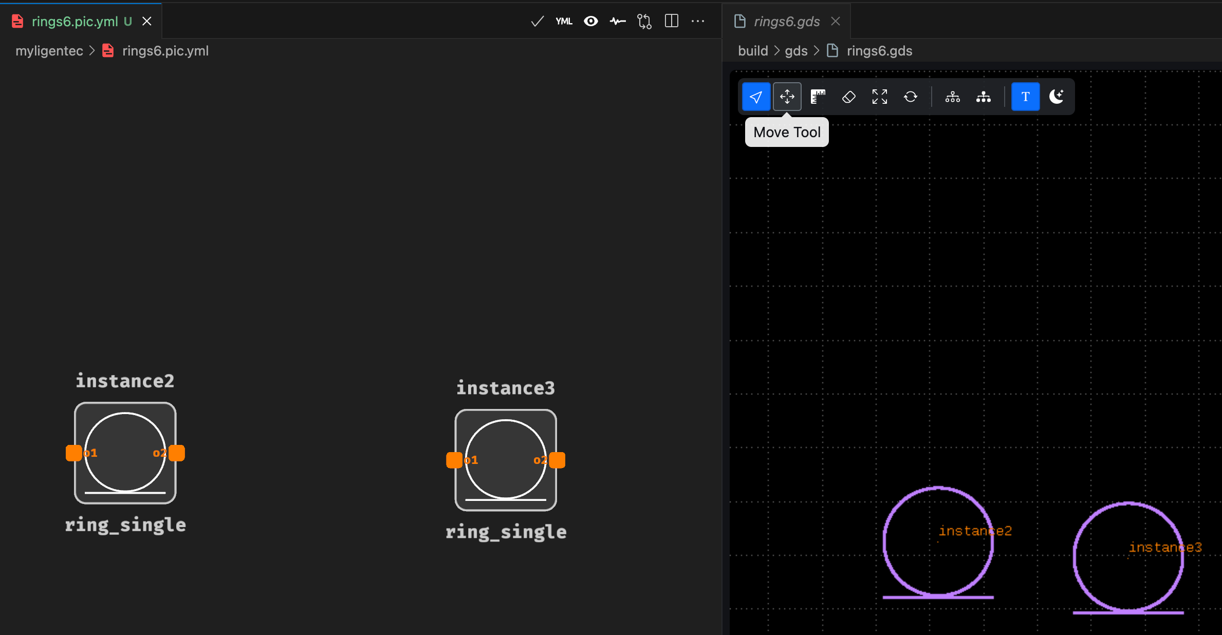
You should see something like the following image, where the Schematic View is on the left, and the GDS View is on the right. Make sure you have enough space between the rings for a route with 2 bends. Otherwise, click move and then move one of the rings.
-
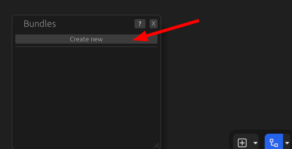
Press
bto place an auto-route between both components.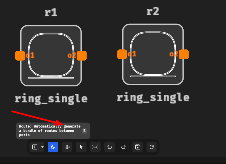
Use the default parameters. You can change radius or any other setting later.
-
Link port
o2fromr1with porto1fromr2to create an auto-route.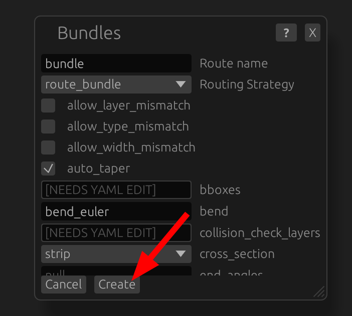
-
Right click each of the outer ports and then press
Expose port. Another option is to presspto select theAdd Porttool and manually add ports namedo1(input) ando2(output).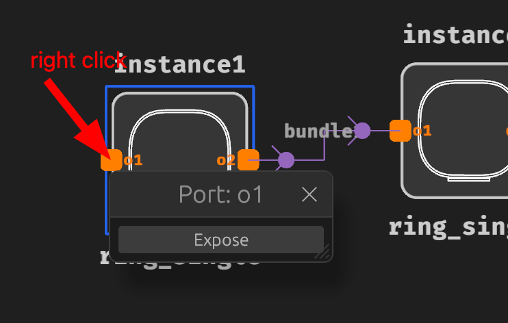
You can see the ports by pressing
Show Ports:
Simulate the circuit
-
In the right top bar of the
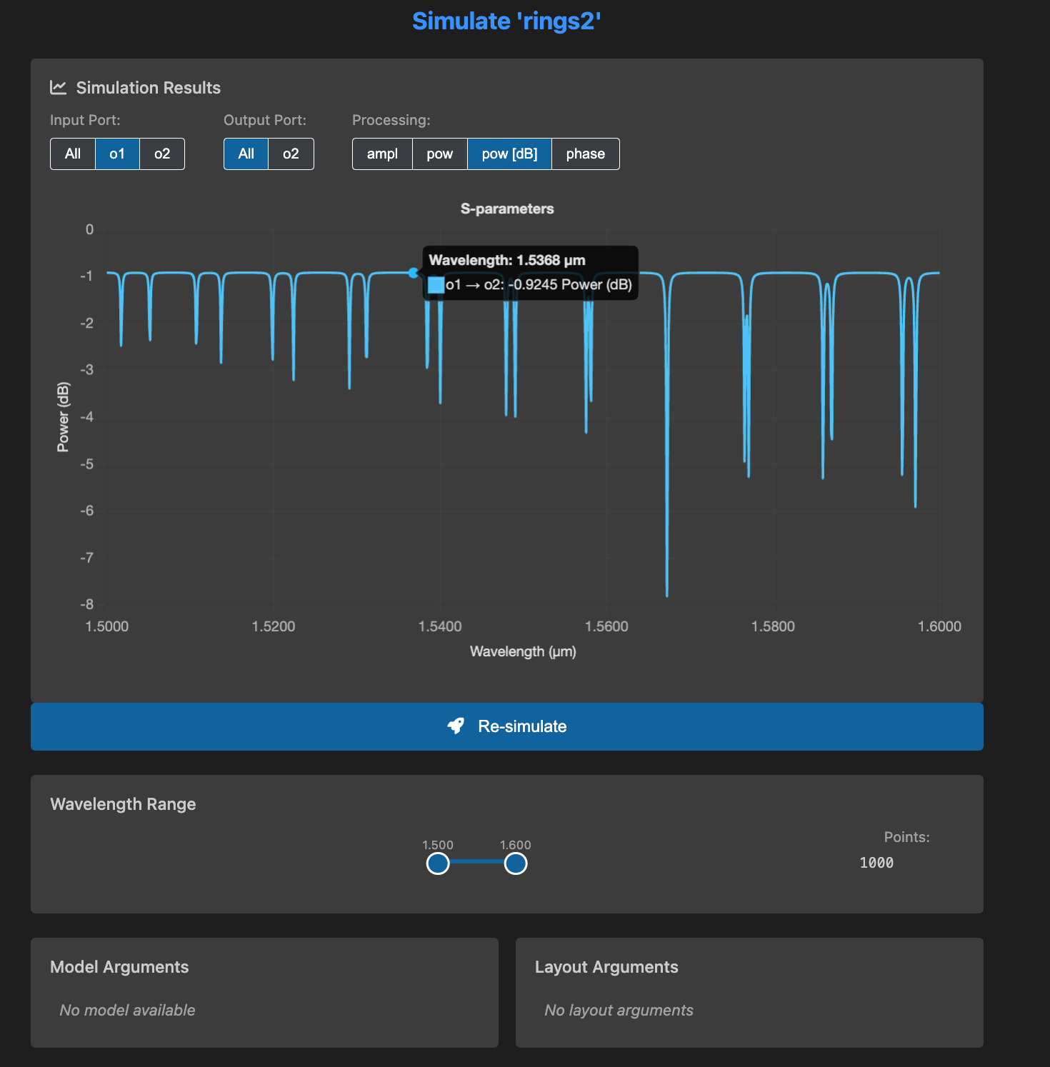
Schematic Viewtab, click the button with the graph icon, hover the Simulate & Plot option, then select the From Layout option to run the simulation (if you can't see the graph button, make sure you are in theSchematic Viewand that the tab is selected).A new tab will appear with the simulation results:
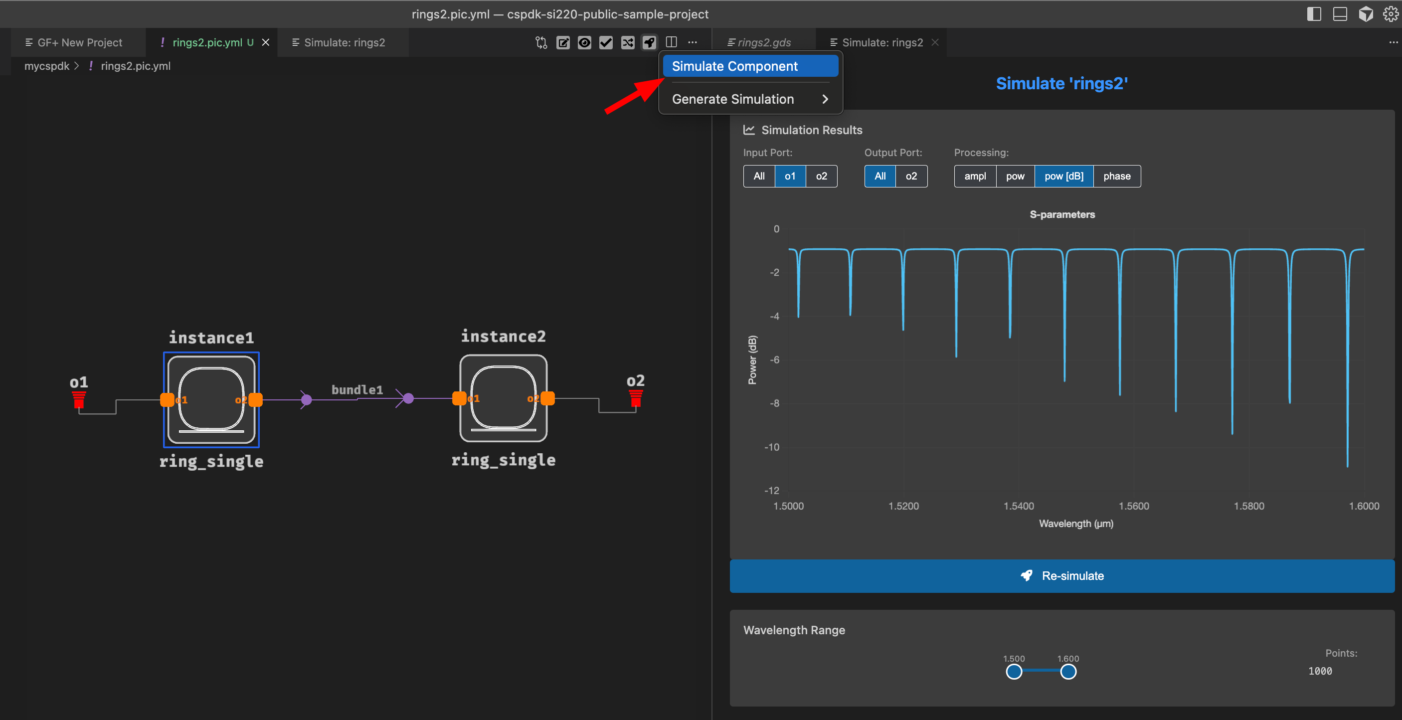
-
In the
Schematic Viewtab, right click onr2and select edit. Set the radius ofr2to 11 um, then pressenter.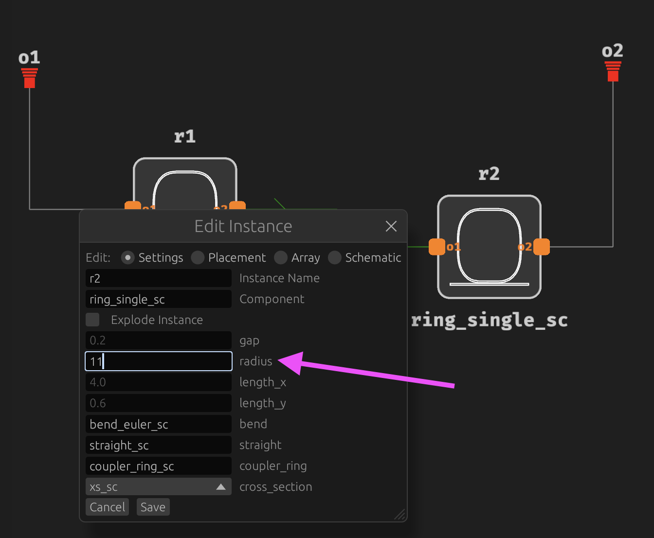
You can see the radius change in the
GDS Viewtab: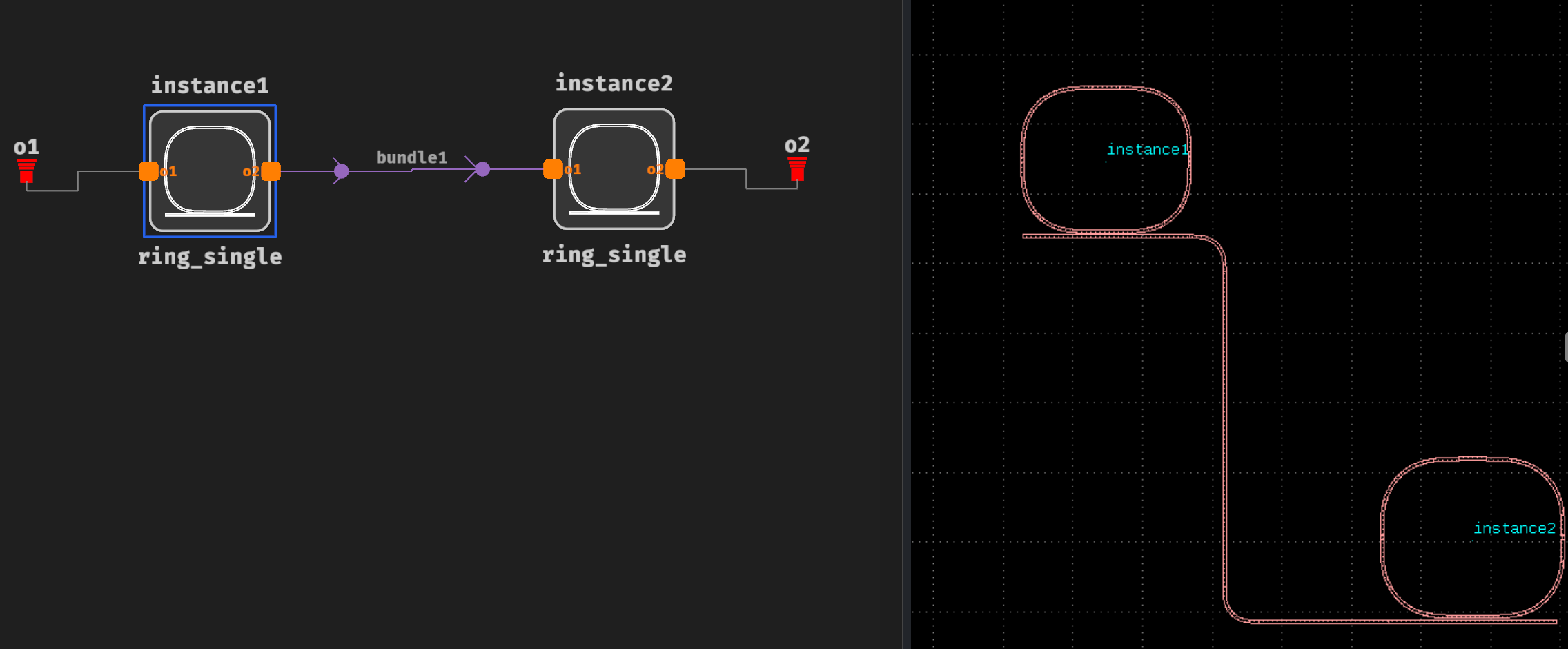
-
Run the simulation again by repeating the actions above. See how both ring resonances only filter one wavelength now at 1565 nm.
Advanced routing (optional)
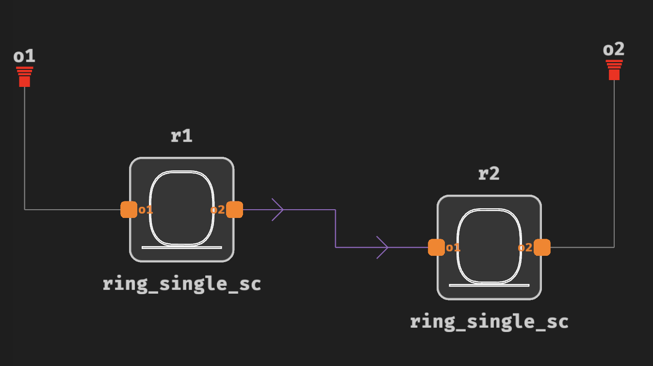
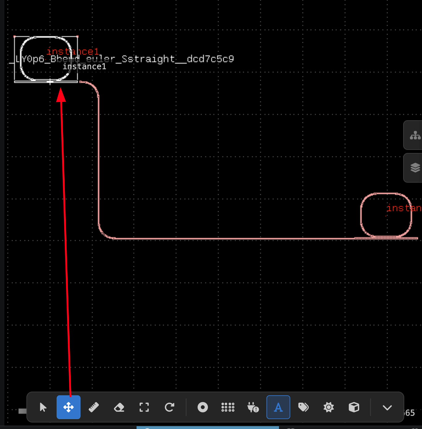
When you right click a link and press edit, you can select Route as the type of link (press enter for it to take effect). Routes are shown in light purple color. See image below.
Now you can move any ring in the layout (the GDS View) by using the move tool, clicking on the ring that you want to move and moving it to the top right.
See video below for learning about more complex routing functions (some elements of the Visual Studio Code extension have been updated since the recording of this video).
Bonus: Add a package for the device (optional)
Create a new schematic rings1package:
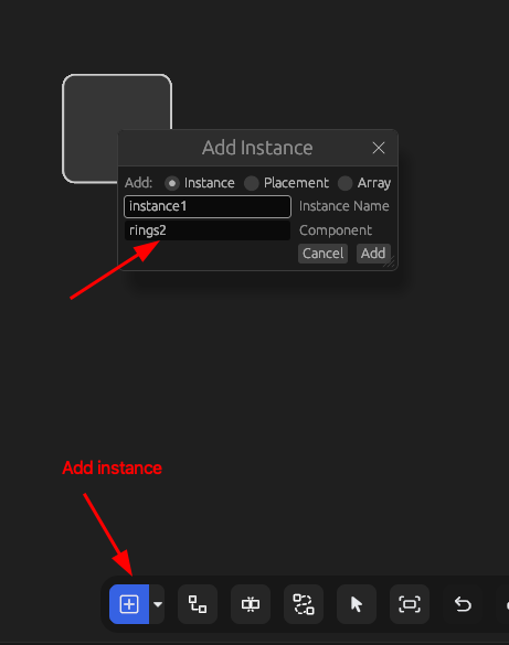
Add an instance:
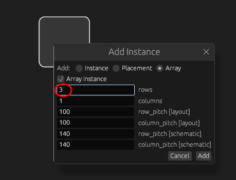
Edit the instance to use an array of 3 elements at 150 um pitch:
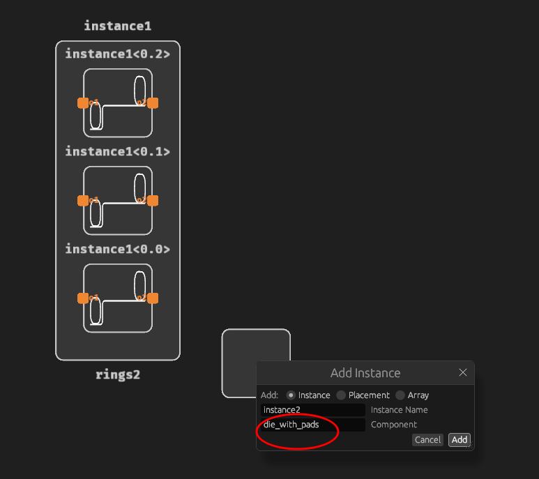
Add a die_with_pads instance:
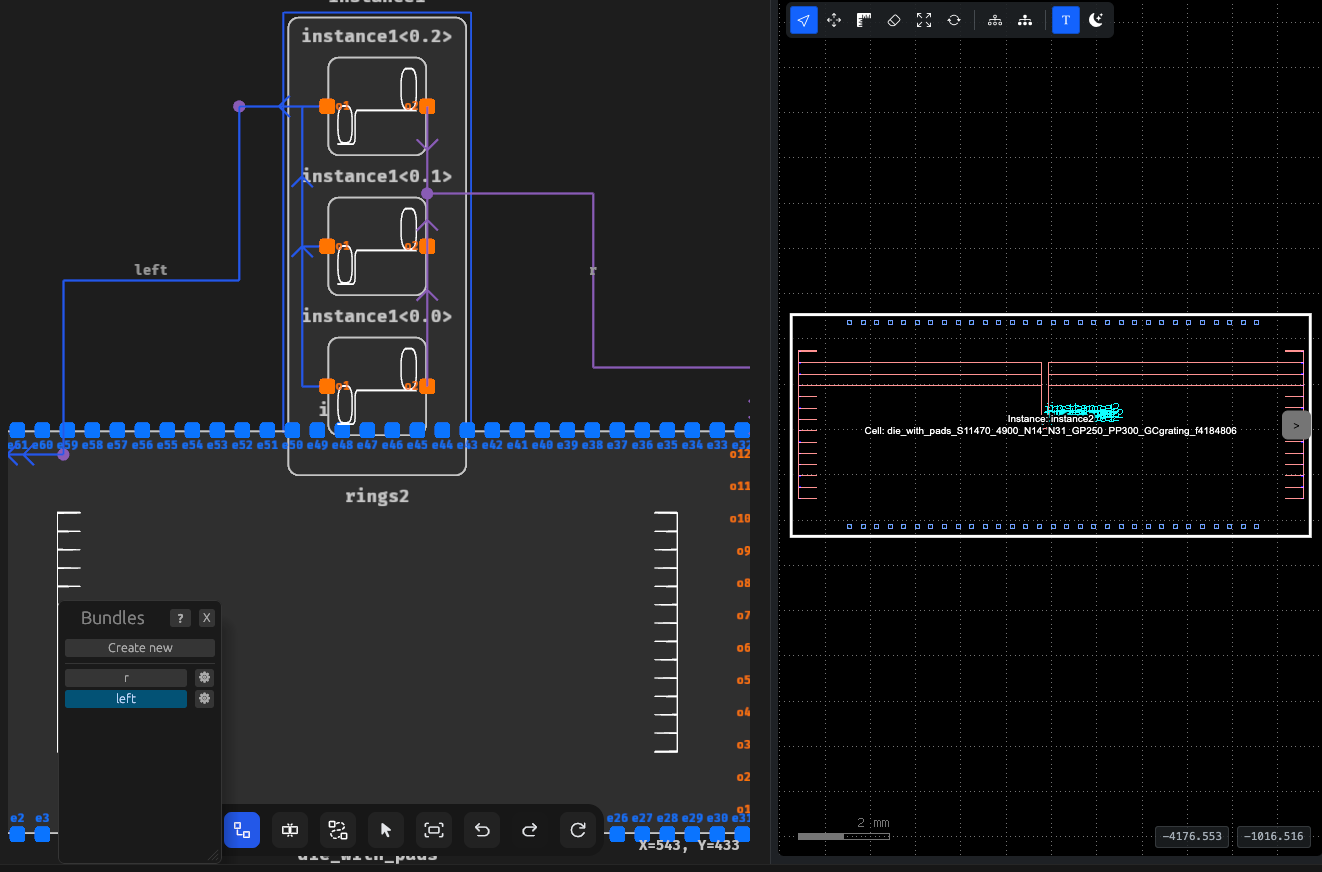
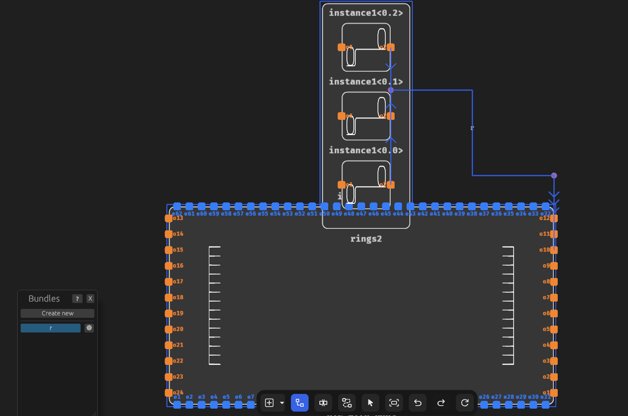
Define 2 groups of routes (bundles) — left for left routes and right for right routes:
Then click on Show GDS:
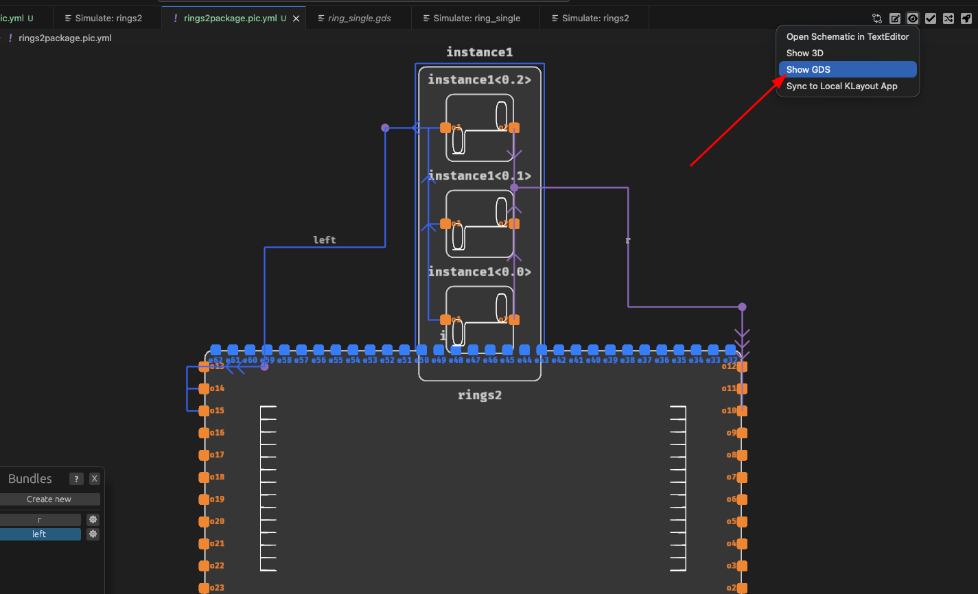
You should see 2 groups of routes and a fully packaged device: