Running Palace Simulations: Spiral Inductor and RLC Model Fit
Palace is an open-source 3D electromagnetic simulator supporting eigenmode, driven (S-parameter), and electrostatic simulations. This notebook demonstrates using the gsim.palace API to run a driven simulation on a spiral inductor with Metal1 guard ring, and fitting the resulting S-parameters to an RLC equivalent circuit model for use in circulax.
Requirements:
- IHP PDK: uv pip install ihp-gdsfactory
- gsim with Palace backend
- circulax: pip install circulax
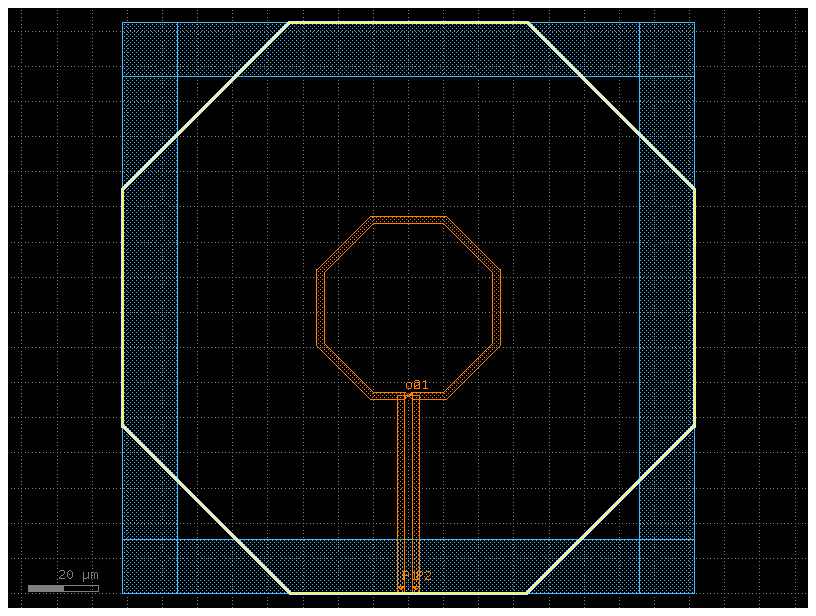
Build inductor + guard ring
Known PDK limitation: gf.components.inductor accepts a turns parameter but does not use it in geometry construction. The spiral is always single-turn regardless of the value passed.
# Config: filepaths, PDK activation, package imports and selected source
import gdsfactoryplus as gfp

pdk = gfp.get_pdk()
pdk.activate()
import gdsfactory as gf
from ihp import PDK

PDK.activate()

c = gf.components.inductor(
    width=2,
    space=2.1,
    diameter=50,
    turns=1,
    layer_metal="TopMetal2drawing",
    layer_inductor="INDdrawing",
    layer_metal_pin="TopMetal2drawing",
    layers_no_fill=("NoMetFillerdrawing",),
).copy()

# Define guard ring dimensions based on the inductor's bounding box
bbox = c.bbox()
xmin, ymin = bbox.left, bbox.bottom
xmax, ymax = bbox.right, bbox.top

margin_outer = 0.0
margin_inner = -15.0

xlo, xro = xmin - margin_outer, xmax + margin_outer
ybo, yto = ymin - margin_outer, ymax + margin_outer
xli, xri = xmin - margin_inner, xmax + margin_inner
ybi, yti = ymin - margin_inner, ymax + margin_inner

w_v = xli - xlo  # Width vertical walls
h_h = yto - yti  # Height horizontal walls
over = 0.5  # Overlap for Gmsh to fuse the pieces

# Left wall
c.add_ref(
    gf.components.rectangle(
        size=(w_v + over, yto - ybo), layer="Metal1drawing", centered=True
    )
).move((xlo + w_v / 2 + over / 2, (yto + ybo) / 2))
# Right wall
c.add_ref(
    gf.components.rectangle(
        size=(w_v + over, yto - ybo), layer="Metal1drawing", centered=True
    )
).move((xro - w_v / 2 - over / 2, (yto + ybo) / 2))
# Top wall
c.add_ref(
    gf.components.rectangle(
        size=(xro - xlo, h_h + over), layer="Metal1drawing", centered=True
    )
).move(((xro + xlo) / 2, yto - h_h / 2 - over / 2))
# Bottom wall
c.add_ref(
    gf.components.rectangle(
        size=(xro - xlo, h_h + over), layer="Metal1drawing", centered=True
    )
).move(((xro + xlo) / 2, ybo + h_h / 2 + over / 2))

cc = c.copy()

c.draw_ports()
c.plot()
Configure and run simulation with DrivenSim
from gsim.palace import DrivenSim

# Create simulation object
sim = DrivenSim()

# Set output directory
sim.set_output_dir("./palace-sim-inductor")

# Set the component geometry
sim.set_geometry(cc)

# Configure layer stack from active PDK
sim.set_stack(substrate_thickness=180.0, include_substrate=True)

# Configure ports
sim.add_port(
    "P1", from_layer="metal1", to_layer="topmetal2", geometry="via", excited=True
)
sim.add_port(
    "P2", from_layer="metal1", to_layer="topmetal2", geometry="via", excited=True
)

# Configure driven simulation (frequency sweep for S-parameters)
sim.set_driven(fmin=10e9, fmax=200e9, num_points=50)

# Validate configuration
print(sim.validate_config())
# Generate mesh (presets: "coarse", "default", "fine")
sim.set_airbox(margin_x=50, margin_y=50, z_above=50, z_below=5)
sim.mesh(preset="default", refined_mesh_size=1.5)
21:17:41 | WARNING | Small conductor feature detected (2.000 um) may be under-resolved by refined_mesh_size=1.500 um. The heuristic target is <= 1.000 um (2 cells/feature). Reduce refined_mesh_size; auto_size=True preserves an explicit size.
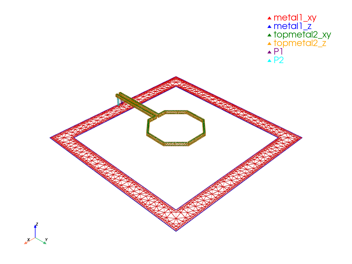
Mesh Summary
========================================
Dimensions: 262.6 x 262.6 x 250.9 µm
Nodes:      22,430
Elements:   167,881
Tetrahedra: 126,378
Edge length: 0.42 - 86.86 µm
Quality:    0.584 (min: 0.009)
SICN:       0.633 (all valid)
Worst element distortion, κ: 105.862 (tet centers; 1 is ideal)
Estimated Field DOFs: 805,126 (order 2; before Palace preprocessing)
Mesh hash:  sha256:f282a49bc19c5eb7  (gmsh 4.15.2, gsim 0.9.0)
Mesher:     2D algorithm 5, 3D algorithm 1, threads 1 (1D/2D/3D limits 1/1/1)
----------------------------------------
Volumes (4):
  - silicon [1]
  - sio2 [2]
  - sin [3]
  - air [4]
Surfaces (12):
  - metal1_xy [5]
  - metal1_z [6]
  - topmetal2_xy [7]
  - topmetal2_z [8]
  - P1 [9]
  - P2 [10]
  - air__silicon [11]
  - silicon__sio2 [12]
  - air__sio2 [13]
  - sin__sio2 [14]
  - air__sin [15]
  - air__None [16]
----------------------------------------
Mesh:   palace-sim-inductor/palace.msh
Run simulation on cloud
palace-8e134a93  [####################]  Job completed  elapsed 0m 00s
Extracting results.tar.gz...
Downloaded 13 files to /home/runner/work/simulation-templates/simulation-templates/docs/notebooks/sim-data-palace-8e134a93
Analytical RLC Model Fit
Extract Differential Impedance
We assemble the S-parameter matrix from the simulation results into a scikit-rf Network object, which handles the conversion to Z-parameters. From the 2×2 Z-matrix we compute the differential impedance \(Z_\text{diff} = Z_{11} - Z_{12} - Z_{21} + Z_{22}\), which is the impedance seen between the two ports of the inductor under differential excitation.
import numpy as np
import skrf as rf

f = results.freq * 1e9  # GHz -> Hz
w = 2 * np.pi * f

ports = results.port_names
n = len(ports)

S = np.zeros((len(f), n, n), dtype=complex)
for i, pi in enumerate(ports):
    for j, pj in enumerate(ports):
        S[:, i, j] = results[(pi, pj)].complex

ntwk = rf.Network(f=f, s=S, f_unit="hz")
Z = ntwk.z

Z_sim = Z[:, 0, 0] - Z[:, 0, 1] - Z[:, 1, 0] + Z[:, 1, 1]
f_sim = f
RLC Model Definition
We fit an RLC equivalent circuit model to the simulated impedance data. The inductor is modeled as a series RL branch in parallel with a parasitic capacitance C:
The total impedance is:
We define the RLC impedance as a function of frequency. The total admittance (inverse of impedance) is the sum of the admittance of the series RL branch and the parasitic capacitance:
We rewrite the RLC impedance in normalized form. Defining \(\tilde\omega = \omega/\omega_0\), the dimensionless impedance is:
so that \(Z(f) = R \cdot z(f/f_0, Q)\).
The loss function measures the total squared error between the model and the simulated data across all frequencies:
This is a real-valued scalar that JAX will differentiate with respect to \(f_0\), \(Q\), and \(R\) to drive the optimization.
import jax
import jax.numpy as jnp

jax.config.update("jax_enable_x64", True)


# The RLC impedance function
def z_rlc(w, Q):
    return (1 + 1j * w * Q) / (1 - w**2 + 1j * w / Q)


f_jnp = jnp.array(f_sim, dtype=jnp.float64)
Z_target = jnp.array(Z_sim, dtype=jnp.complex128)


@jax.jit
def loss_fn(param):
    z_fit = param[2] * z_rlc(f_jnp / param[0], param[1])
    z_err = Z_target - z_fit
    return jnp.real(jnp.sum(z_err * jnp.conj(z_err)))
Initial Parameter Estimation
We estimate the initial values of \(R\), \(L\), and \(C\) directly from the data before running the optimization. Good initial values help the optimizer converge faster and avoid local minima.
- \(f_0\) is read from the frequency at which \(|Z|\) is maximum
- \(R \approx \text{Re}(Z)|_{f \to 0}\), the low-frequency resistance
- \(Q\) is estimated from the -3 dB bandwidth: \(Q = f_0 / \Delta f\), where \(\Delta f\) is the width of the peak above \(|Z|_\text{max}/\sqrt{2}\)
absZ = np.abs(Z_sim)
f0_ini = float(f_sim[np.argmax(absZ)])
R_ini = float(Z_sim.real[0])
mask = absZ > np.max(absZ) / np.sqrt(2)
Q_ini = f0_ini / np.ptp(f_sim[mask]) if mask.sum() > 1 else 5.0
par_ini = jnp.array([f0_ini, Q_ini, R_ini])

print(f"f0 = {f0_ini / 1e9:.3f} GHz | Q = {Q_ini:.3f} | R = {R_ini:.4f} Ohm")
Optimization
We minimize the squared error between the model and the data over all frequencies using the Adam optimizer.
At each step, Adam computes the gradient \(\nabla_\theta \mathcal{L}\) automatically via JAX autodiff and updates the parameters:
import optax

optimizer = optax.adam(learning_rate=0.05)
opt_state = optimizer.init(par_ini)
vg_fn = jax.jit(jax.value_and_grad(loss_fn))
vg_fn(par_ini)

par = par_ini
for step in range(1000):
    loss, grads = vg_fn(par)
    if step % 200 == 0:
        print(
            f"step {step:4d}: f0={float(par[0]) / 1e9:.4f} GHz  Q={float(par[1]):.3f}  R={float(par[2]):.4f}  loss={float(loss):.3e}"
        )
    updates, opt_state = optimizer.update(grads, opt_state)
    par = optax.apply_updates(par, updates)

f0_fit, Q_fit, R_fit = float(par[0]), float(par[1]), float(par[2])
step    0: f0=168.9796 GHz  Q=5.000  R=0.9698  loss=3.352e+07
step  200: f0=168.9796 GHz  Q=16.452  R=10.2524  loss=6.940e+06
step  400: f0=168.9796 GHz  Q=19.681  R=7.8232  loss=5.273e+06
step  600: f0=168.9796 GHz  Q=23.036  R=6.1745  loss=4.159e+06
step  800: f0=168.9796 GHz  Q=25.840  R=5.1966  loss=3.577e+06
Recover L and C
Once converged, \(L\) and \(C\) are recovered analytically from the fitted \((f_0, Q, R)\) using the RLC resonance relations:
where \(\omega_0 = 2\pi f_0\).
w0 = 2 * np.pi * f0_fit
tau = Q_fit / w0
L_fit = tau * R_fit
C_fit = 1 / (L_fit * w0**2)

print(f"R = {R_fit:.6f} Ohm")
print(f"L = {L_fit * 1e12:.4f} pH")
print(f"C = {C_fit * 1e15:.4f} fF")
print(f"f0 = {f0_fit / 1e9:.4f} GHz  Q = {Q_fit:.3f}")
Results
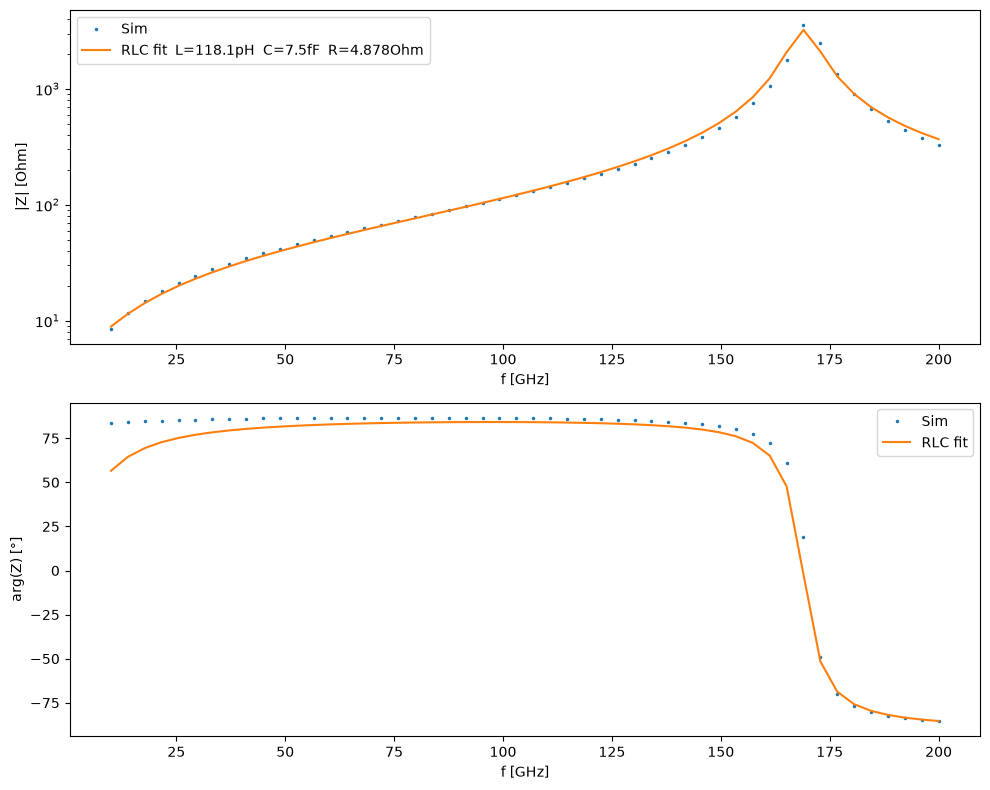
We evaluate the fitted model across the full frequency range and compare it against the simulation data. The two plots show the magnitude \(|Z(f)|\) on a log scale and the phase \(\arg(Z(f))\) in degrees — a good fit should reproduce both the inductive rise, the resonance peak, and the phase transition.
import matplotlib.pyplot as plt

print(f"\nR = {R_fit:.6f} Ohm")
print(f"L = {L_fit * 1e12:.4f} pH")
print(f"C = {C_fit * 1e15:.4f} fF")
print(f"f0 = {f0_fit / 1e9:.4f} GHz  Q = {Q_fit:.3f}")

Z_fit = np.array([R_fit * z_rlc(f / f0_fit, Q_fit) for f in f_sim])

fig, axes = plt.subplots(2, 1, figsize=(10, 8))
axes[0].plot(f_sim / 1e9, np.abs(Z_sim), ".", ms=3, label="Sim")
axes[0].plot(
    f_sim / 1e9,
    np.abs(Z_fit),
    label=f"RLC fit  L={L_fit * 1e12:.1f}pH  C={C_fit * 1e15:.1f}fF  R={R_fit:.3f}Ohm",
)
axes[0].set_yscale("log")
axes[0].set_xlabel("f [GHz]")
axes[0].set_ylabel("|Z| [Ohm]")
axes[0].legend()

axes[1].plot(f_sim / 1e9, np.angle(Z_sim, deg=True), ".", ms=3, label="Sim")
axes[1].plot(f_sim / 1e9, np.angle(Z_fit, deg=True), label="RLC fit")
axes[1].set_xlabel("f [GHz]")
axes[1].set_ylabel("arg(Z) [°]")
axes[1].legend()
plt.tight_layout()
plt.show()
Circulax-Based Inverse Design
Define Circulax Component
With the fitted values from the analytical fit, we define my_inductor as a frequency-domain circulax component using @fdomain_component. The decorator converts the RLC admittance matrix into a two-port component compatible with any circulax netlist.
The admittance matrix for a symmetric two-port is:
The netlist connects the inductor directly between IN and GND — a single-port measurement configuration, consistent with how \(Z_\text{diff}\) was extracted from the simulation.
from circulax import compile_circuit
from circulax.s_transforms import fdomain_component

# Equivalent circuit:
#
#         --- C ---
#        |         |
# p1 ----+---R--L--+---- p2


@fdomain_component(ports=("p1", "p2"))
def my_inductor(f, R=1.0, L=100e-12, C=10e-15):
    w = 2.0 * jnp.pi * f
    Y_RL = 1.0 / (R + 1j * w * L)  # series RL branch
    Y_C = 1j * w * C  # parallel capacitance
    Y = Y_RL + Y_C
    return jnp.array([[Y, -Y], [-Y, Y]], dtype=jnp.complex128)


net_dict = {
    "instances": {
        "GND": {"component": "ground"},
        "L1": {
            "component": "my_inductor",
            "settings": {"R": R_fit, "L": L_fit, "C": C_fit},
        },
    },
    "connections": {
        "L1,p2": "GND,p1",
    },
    "ports": {
        "IN": "L1,p1",
    },
}

models = {"my_inductor": my_inductor, "ground": lambda: 0}

circuit = compile_circuit(net_dict, models)
groups = circuit.groups
freqs = jnp.asarray(f_sim)
Z_target = jnp.asarray(Z_sim)

print("Circuit compiled. System size:", circuit.sys_size)
print("Port map:", circuit.port_map)
Inverse Design with Circulax
We use circulax inside the optimization loop as part of a differentiable inverse design workflow. At each step, we perform a full AC sweep and minimize the discrepancy between the compact-model impedance and the Palace simulation data:
where the impedance is recovered from the simulated reflection coefficient through the standard one-port relation
The optimization is initialized using the analytical RLC fit parameters. To ensure physically meaningful values throughout the optimization, we optimize unconstrained variables and map them to positive parameters using a softplus parameterization:
This enables stable gradient-based optimization using JAX automatic differentiation and Optax optimizers.
from circulax.solvers import setup_ac_sweep
from circulax.utils import update_params_dict

# Port node for IN — check port_map output above
port_node = next(v for k, v in circuit.port_map.items() if k == "IN")


# Positive parametrization
# raw_params -> softplus -> positive physical parameters
def positive(x):
    return jax.nn.softplus(x)


# inverse-softplus
def inv_softplus(y):
    return jnp.log(jnp.exp(y) - 1.0)


def loss_circulax(raw_params):
    params = positive(raw_params)
    R, L, C = params
    g = update_params_dict(groups, "my_inductor", "L1", "R", R)
    g = update_params_dict(g, "my_inductor", "L1", "L", L)
    g = update_params_dict(g, "my_inductor", "L1", "C", C)

    y_op = circuit.with_groups(g)()
    ac = setup_ac_sweep(groups=g, num_vars=circuit.sys_size, port_nodes=[port_node])
    sol = ac(freqs=freqs, y_dc=y_op)

    S11 = sol[:, 0, 0]
    Z_cx = 50.0 * (1 + S11) / (1 - S11)
    err_re = jnp.real(Z_cx) - jnp.real(Z_target)
    err_im = jnp.imag(Z_cx) - jnp.imag(Z_target)
    loss = jnp.mean(err_re**2 + err_im**2)

    return loss


raw_params_ini = inv_softplus(
    jnp.array(
        [
            R_fit,
            L_fit,
            C_fit,
        ]
    )
)

optimizer = optax.adam(1e-2)
opt_state = optimizer.init(raw_params_ini)
vg_fn = jax.jit(jax.value_and_grad(loss_circulax))
vg_fn(raw_params_ini)  # warm-up

raw_params = raw_params_ini
for step in range(500):
    loss, grads = vg_fn(raw_params)
    if step % 20 == 0:
        params = positive(raw_params)
        R_, L_, C_ = params
        print(
            f"step {step:3d}: R={float(R_):.5f} Ohm  L={float(L_) * 1e12:.3f} pH  C={float(C_) * 1e15:.3f} fF  loss={float(loss):.3e}"
        )
    updates, opt_state = optimizer.update(grads, opt_state)
    raw_params = optax.apply_updates(raw_params, updates)

R_fit_cx, L_fit_cx, C_fit_cx = [float(x) for x in positive(raw_params)]
f0_cx = 1.0 / (2 * np.pi * np.sqrt(L_fit_cx * C_fit_cx))
Q_cx = 2 * np.pi * f0_cx * L_fit_cx / R_fit_cx

print(f"\nR = {R_fit_cx:.6f} Ohm")
print(f"L = {L_fit_cx * 1e12:.4f} pH")
print(f"C = {C_fit_cx * 1e15:.4f} fF")
print(f"f0 = {f0_cx / 1e9:.4f} GHz  Q = {Q_cx:.3f}")
step   0: R=4.59498 Ohm  L=121.272 pH  C=7.327 fF  loss=8.046e+04
step  20: R=4.39895 Ohm  L=120.495 pH  C=7.250 fF  loss=1.862e+04
step  40: R=4.20441 Ohm  L=121.114 pH  C=7.241 fF  loss=8.721e+03
step  60: R=4.04092 Ohm  L=121.362 pH  C=7.224 fF  loss=6.392e+03
step  80: R=3.92307 Ohm  L=121.412 pH  C=7.223 fF  loss=5.355e+03
step 100: R=3.84957 Ohm  L=121.213 pH  C=7.236 fF  loss=4.947e+03
step 120: R=3.80556 Ohm  L=120.855 pH  C=7.258 fF  loss=4.651e+03
step 140: R=3.77367 Ohm  L=120.412 pH  C=7.285 fF  loss=4.357e+03
step 160: R=3.74341 Ohm  L=119.941 pH  C=7.313 fF  loss=4.061e+03
step 180: R=3.71169 Ohm  L=119.460 pH  C=7.343 fF  loss=3.767e+03
step 200: R=3.67889 Ohm  L=118.972 pH  C=7.373 fF  loss=3.479e+03
step 220: R=3.64585 Ohm  L=118.479 pH  C=7.404 fF  loss=3.199e+03
step 240: R=3.61297 Ohm  L=117.984 pH  C=7.435 fF  loss=2.931e+03
step 260: R=3.58045 Ohm  L=117.490 pH  C=7.466 fF  loss=2.675e+03
step 280: R=3.54842 Ohm  L=117.000 pH  C=7.498 fF  loss=2.433e+03
step 300: R=3.51701 Ohm  L=116.516 pH  C=7.529 fF  loss=2.205e+03
step 320: R=3.48635 Ohm  L=116.041 pH  C=7.560 fF  loss=1.993e+03
step 340: R=3.45656 Ohm  L=115.575 pH  C=7.591 fF  loss=1.796e+03
step 360: R=3.42770 Ohm  L=115.121 pH  C=7.621 fF  loss=1.615e+03
step 380: R=3.39984 Ohm  L=114.681 pH  C=7.650 fF  loss=1.449e+03
step 400: R=3.37304 Ohm  L=114.254 pH  C=7.679 fF  loss=1.298e+03
step 420: R=3.34732 Ohm  L=113.841 pH  C=7.707 fF  loss=1.160e+03
step 440: R=3.32272 Ohm  L=113.445 pH  C=7.734 fF  loss=1.036e+03
step 460: R=3.29924 Ohm  L=113.064 pH  C=7.760 fF  loss=9.248e+02
step 480: R=3.27690 Ohm  L=112.700 pH  C=7.785 fF  loss=8.253e+02

R = 3.255679 Ohm
L = 112.3525 pH
C = 7.8096 fF
f0 = 169.9081 GHz  Q = 36.841
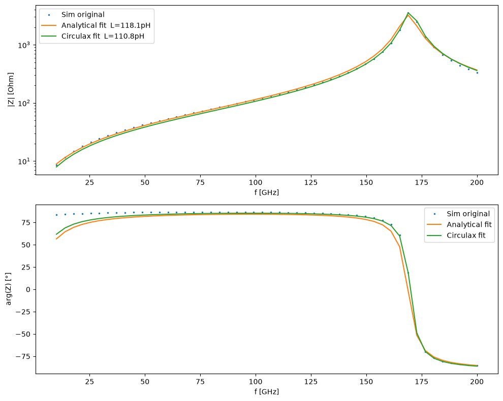
Results
We compare the analytical fit and the circulax inverse design against the original simulation data.
g_final = update_params_dict(groups, "my_inductor", "L1", "R", R_fit_cx)
g_final = update_params_dict(g_final, "my_inductor", "L1", "L", L_fit_cx)
g_final = update_params_dict(g_final, "my_inductor", "L1", "C", C_fit_cx)

y_op_final = circuit.with_groups(g_final)()
ac_final = setup_ac_sweep(
    groups=g_final, num_vars=circuit.sys_size, port_nodes=[port_node]
)
sol_final = ac_final(freqs=freqs, y_dc=y_op_final)

S11_final = sol_final[:, 0, 0]
Z_cx_final = 50.0 * (1 + S11_final) / (1 - S11_final)

fig, axes = plt.subplots(2, 1, figsize=(10, 8))
axes[0].plot(f_sim / 1e9, np.abs(Z_sim), ".", ms=3, label="Sim original")
axes[0].plot(
    f_sim / 1e9, np.abs(Z_fit), label=f"Analytical fit  L={L_fit * 1e12:.1f}pH"
)
axes[0].plot(
    f_sim / 1e9, np.abs(Z_cx_final), label=f"Circulax fit  L={L_fit_cx * 1e12:.1f}pH"
)
axes[0].set_yscale("log")
axes[0].set_xlabel("f [GHz]")
axes[0].set_ylabel("|Z| [Ohm]")
axes[0].legend()

axes[1].plot(
    f_sim / 1e9, np.angle(np.array(Z_sim), deg=True), ".", ms=3, label="Sim original"
)
axes[1].plot(f_sim / 1e9, np.angle(np.array(Z_fit), deg=True), label="Analytical fit")
axes[1].plot(
    f_sim / 1e9, np.angle(np.array(Z_cx_final), deg=True), label="Circulax fit"
)
axes[1].set_xlabel("f [GHz]")
axes[1].set_ylabel("arg(Z) [°]")
axes[1].legend()
plt.tight_layout()
plt.show()