· GDSFactory Team
Introducing GDSFactory+ 2.0
A new schematic editor, a proper Python SDK, better simulation and verification, and an AI agent that can work directly with your chip design.
Today we are releasing GDSFactory+ 2.0.
This is a big update. We rebuilt much of the application, introduced a new schematic format and editor, turned the Python package into a proper SDK, and connected simulation, verification, and the AI agent more closely to the design itself.
The practical result is that there are fewer handoffs. You can sketch a circuit, turn it into layout, simulate it, run checks, and inspect the results all seamlessly within one environment.
GDSFactory+ still sits on top of the open-source GDSFactory ecosystem, and Python is still central to how it works. What has changed is how much of the design flow is now available in one place—and how easily you can move between the visual and code-based parts of it.
A new schematic editor
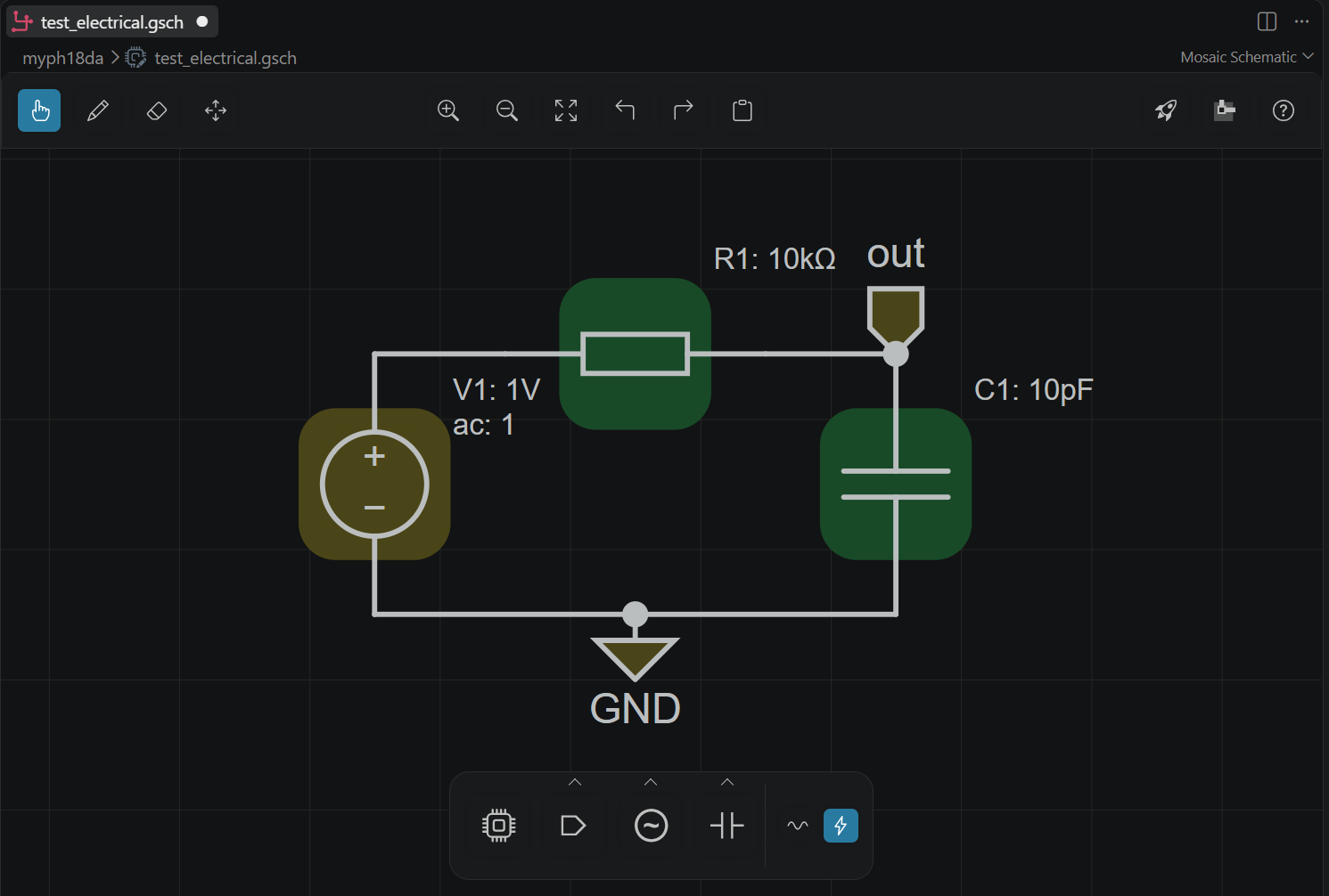
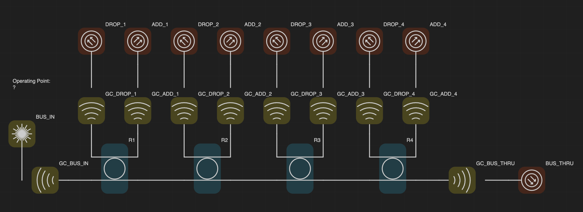
The most visible change in GDSFactory+ 2.0 is our new schematic editor. It has been redesigned from the ground up to be easier to use and to more cleanly and aesthetically represent a wide variety of circuits, from photonic and electronic to quantum-RF.
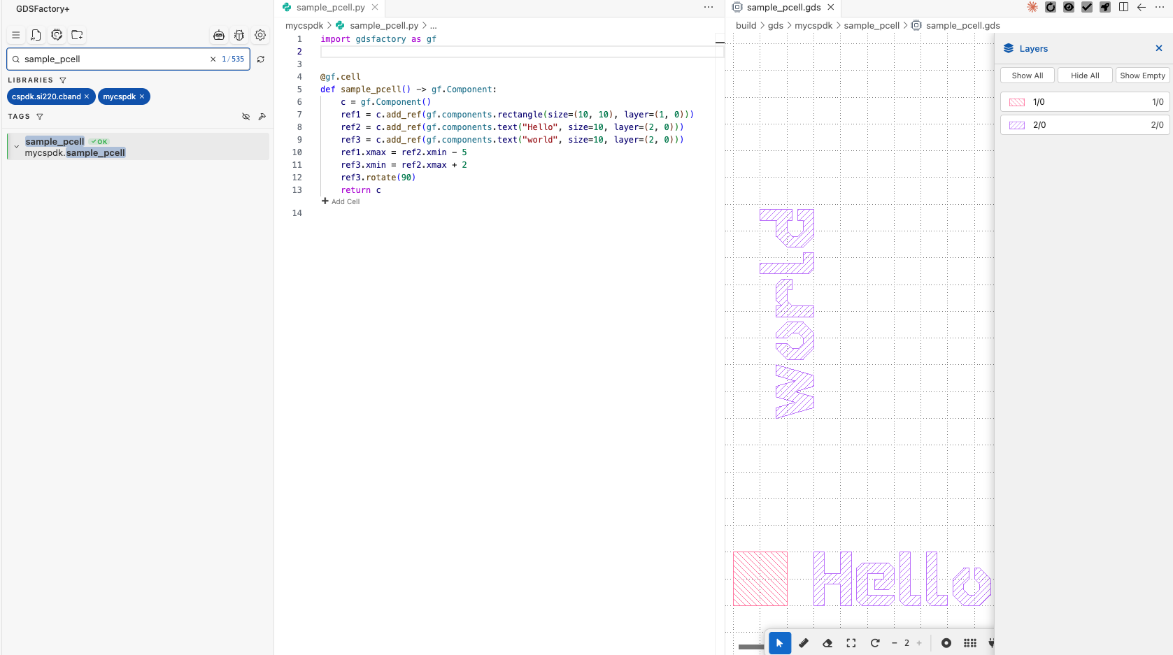
Components are easier to find. The library is grouped by PDK, and a searchable picker gives access to project cells, built-in GDSFactory cells, and foundry components without mixing them into one long list. Tags allow you to further categorize your cells and find them quickly.
Wiring has been made more intuitive and expressive. Click a port and start drawing. Optical routes use Manhattan geometry that can inform layout. Routes can taper between different widths, use s-bends, and preserve their settings when the schematic is reopened.
We also put a lot of care into refining the small interactions that make editing a real circuit less frustrating. Copying components now brings their routes with them. Rotated cells have the correct routing obstacles. You can expose an unconnected port from the canvas, pin reference geometry so it cannot be moved accidentally, and edit a selection from a toolbar that appears next to it.
These are not headline features on their own. But together they add up to a more pleasant experience for the user.
From schematic to layout with Livewire
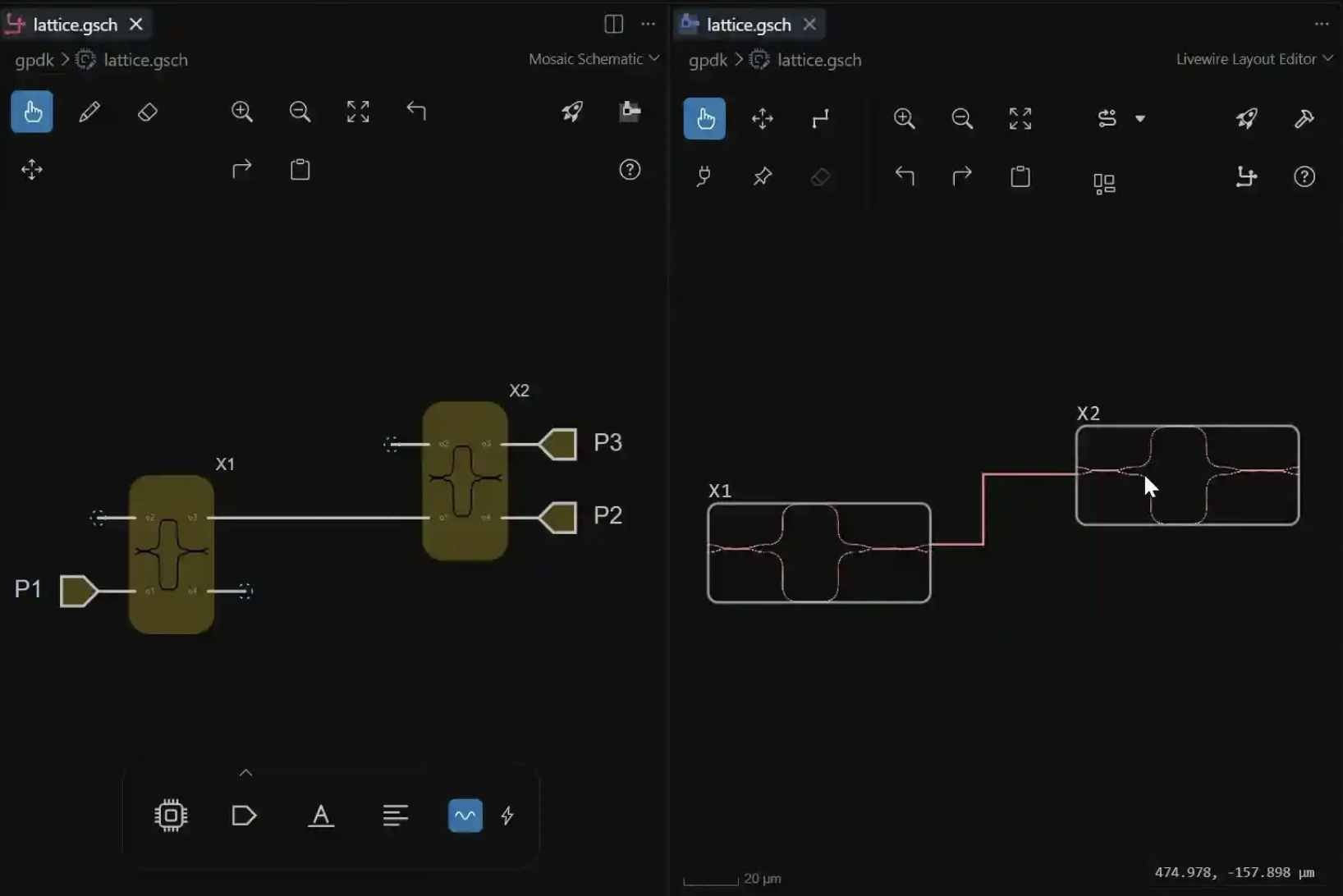
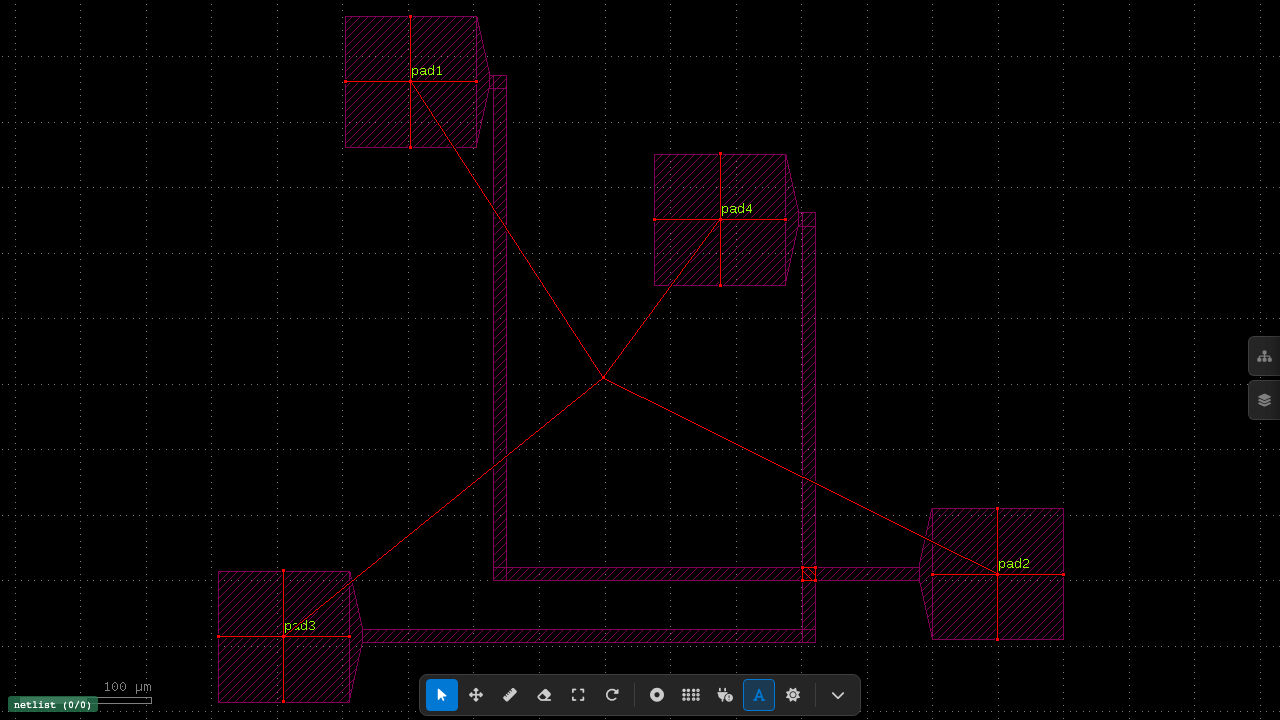
A schematic in GDSFactory+ is not just a drawing. It carries the component parameters, ports, connectivity, and routing information used to produce the layout. Livewire turns that information into a layout that faithfully recreates the real GDS while remaining interactive.
Instead of moving back and forth between an abstract circuit diagram and a separate layout tool, you can position, align, and group components in an interface that shows their true geometry. This makes more complex layout scenarios easier to explore without losing the connection to the underlying design.
The wires drawn in the schematic define which ports connect. It is in Livewire that those connections materialize as physical routes against the real component geometry. Its advanced ML routing engines can find paths through dense layouts, avoid components and other obstacles, and be tuned to the requirements of the design. Different routing methods can be used for different connections, including path-length matching for circuits where timing or phase matters.
The generated route is still easy to modify by hand. You can move a route, add vertices to guide it through a particular area, or convert an individual section into an s-bend. This keeps automated routing from becoming a black box: the engine handles the difficult first pass, while the designer retains direct control over the result.
The result remains tied to the generated GDS. Change a ring radius or waveguide cross-section and Livewire shows the physical effect. Move a component and its attached route moves with it. Change the minimum bend radius and the router uses the new value rather than silently falling back to a default.
The same approach works for hierarchical circuits. A subcircuit can be used as a component in a larger design, while simulation and verification still have access to its underlying connectivity.
GDSFactory+ is now a real Python SDK
Until now, most GDSFactory+ capabilities were reached through the extension. In 2.0, gdsfactoryplus is an installable Python package with platform wheels, type information, and a compiled native core.
The SDK exposes routing, simulation, and verification directly to Python:
from gdsfactoryplus.check import check_connectivity, check_drc, check_lvs
from gdsfactoryplus import routing
from gdsfactoryplus.sim import run_simulation
You can use these APIs in a notebook, a CI job, an internal design script, or any other Python workflow. The verification package includes local optical and electrical connectivity checks, LVS, and remote DRC submission. The routing package brings together manual, step-based, corner-based, A*, bundle, and path-length-matched routing tools.
There is also an API for larger autodesign campaigns. It can submit a campaign to the server, stream typed progress events, and retrieve the results—including useful output from runs that did not complete successfully.
This matters because the graphical application should not become a boundary around the work. If a process is worth repeating, it should be possible to automate it.
Three circuit simulation engines
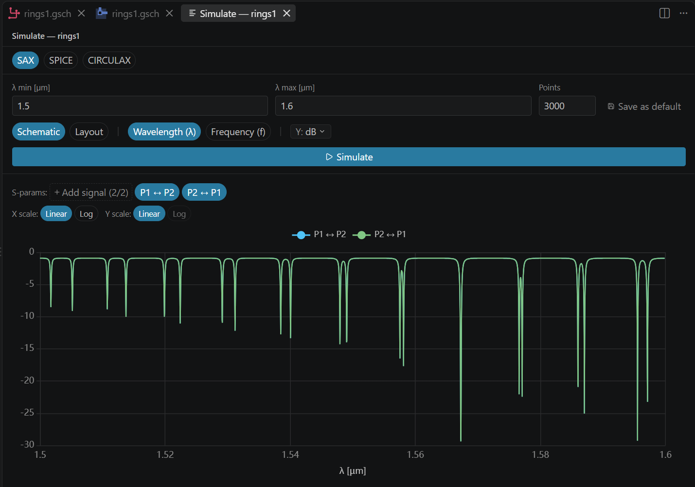
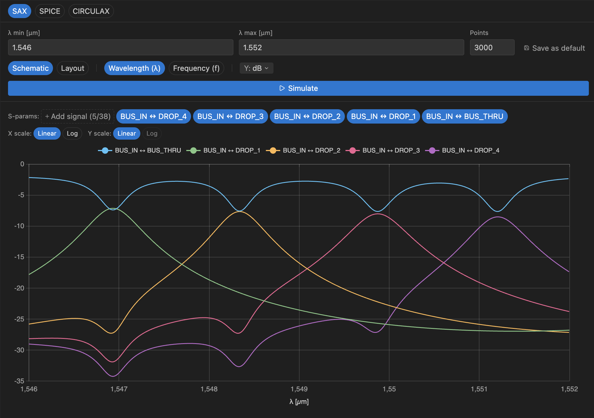
CirculaX joins SAX and SPICE in GDSFactory+ 2.0. Together, they cover photonic frequency-domain simulation, electronic circuit simulation, and mixed electro-optic circuits.
The new simulation dashboard uses the same basic controls across all three engines. You can select signals, change axis scales and units, export results to CSV, and run multi-axis parameter sweeps. Project-level wavelength and frequency ranges are saved, while still allowing a one-off override for a particular run.
The application also checks the circuit before starting. A SAX simulation needs enough ports. A SPICE circuit needs a ground reference. CirculaX needs an emitter. If a model is missing, the dashboard says which one instead of opening an empty plot or failing later in the job.
Models can be added from a component card. GDSFactory+ creates a SAX, CirculaX, or SPICE starter in the project, even when the component itself comes from an installed PDK. This lets you add or replace a model without modifying the original package.
DRC, LVS, and connectivity in the same loop
Verification results are much more useful when they point back to the thing that needs fixing.
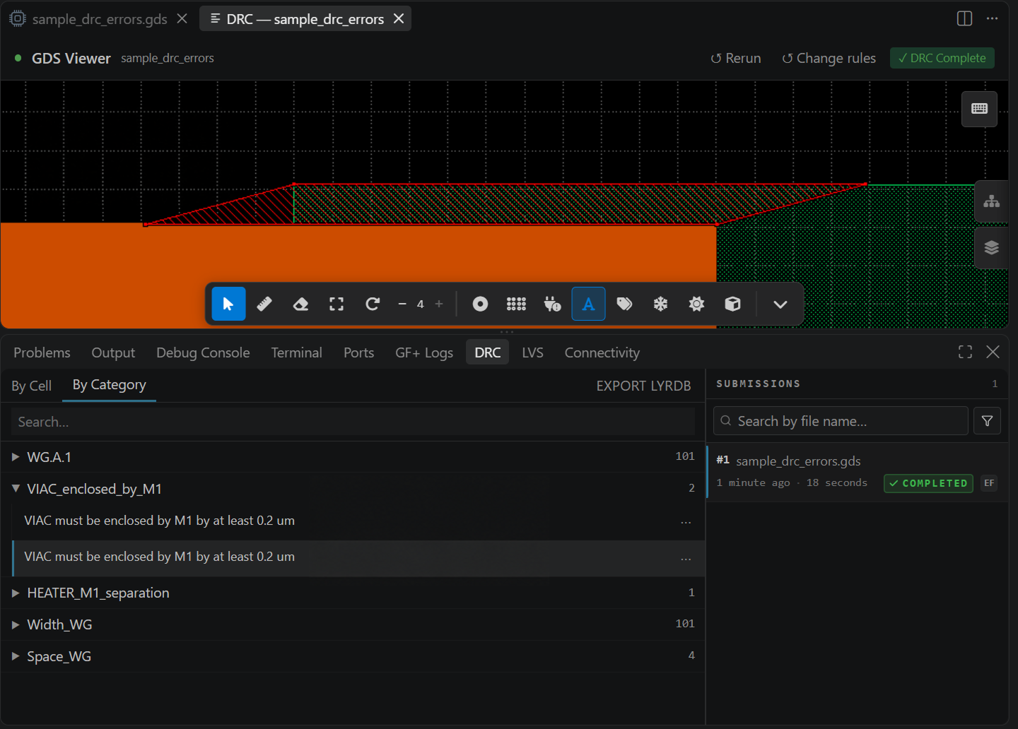
GDSFactory+ 2.0 adds an optical and electrical connectivity check with its own results panel. Findings can be grouped by cell or category, searched, and cross-probed in the design. Previous runs stay available, which makes it easier to check whether an edit actually removed the problem.
LVS now follows the same results pattern as DRC. It uses the logical instance names from the schematic and places markers in the relevant view. Instead of reading a report and then hunting for the corresponding geometry, you can select a finding and go to it.
All three checks—DRC, LVS, and connectivity—are available during the normal design cycle. They do not need to wait until the circuit is considered finished. Connectivity is also available locally through the SDK and as a tool for the AI agent.
An agent that can work on the design
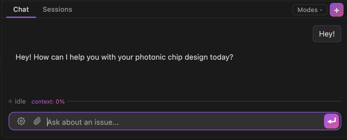
The AI agent has changed substantially in this release. It can read a schematic, inspect the available PDK cells, edit component settings and connections, build the layout, and run DRC or connectivity checks.
For example, you can ask it what 1x2 splitters are available in the active PDK, have it compare their parameters, place one in a circuit, and then check the result. It can also create a schematic from a compact ASCII description, which is useful for drafting a circuit quickly before arranging it by hand.
There are now separate Design and Support modes. Design mode has tools for working with the circuit and PDK. Support mode focuses on the application environment and logs, so it can help diagnose a broken setup without mixing those tools into a design task.
The agent can use supported hosted models, bring-your-own-key providers (for both Anthropic and OpenAI), and custom local MCP servers. Actions that change files or run commands remain visible and subject to approval, and custom tool activity is recorded locally.
We do not expect every design task to begin with a prompt. Often it is faster to drag a component or edit a line of Python. The agent is there for the parts that benefit from searching a large library, explaining an unfamiliar result, or carrying out a sequence of repetitive steps.
Less setup, clearer failures
Some of the largest changes in 2.0 are deliberately hard to notice.
New blank projects now set themselves up after the folder reload. UV is installed through its official platform installers. PDK and site-package sources open read-only, so following a component definition does not risk changing an installed dependency. Project code remains editable.
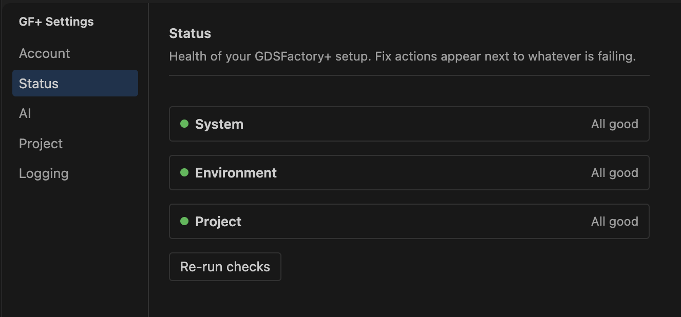
Settings that used to be spread across menus now share one editor. Global and project settings are clearly marked, and the same place shows the active PDK, simulation ranges, AI provider, logging options, and system health. When it changes project configuration, the editor updates pyproject.toml without removing comments or unrelated settings.
The server, Python workers, PDK index, and component cache were also reworked to be faster and more robust. When errors do happen, the messages are better and the consequences are more tightly confined so that you can keep going with the rest of your design.
Before upgrading: schematics have changed
Version 2 uses the new .gsch format. Version 1 schematics used .pic.yml.
The formats are different enough that an existing schematic cannot be migrated by changing its extension. It needs to be converted or recreated in the new editor. We know this creates work for teams with existing designs, and it is the main thing to plan for before upgrading.
The format change gave us room to support electronic and photonic capture in the same editor, make routing more predictable, and carry richer connectivity into simulation and verification. Still, if you have a large v1 project, review the schematic migration guidance and keep a copy of the original project before moving it to 2.0.
Getting started
GDSFactory+ 2.0 is available as a local VS Code extension and through GDSFactory Cloud. Existing users can update to the 2.0 release. New teams can request a trial and begin with one of the sample projects.
The quickstart covers the main workflow: create a component, design and simulate a circuit, run DRC and LVS, and work with the agent. For the full list of changes, including smaller fixes and compatibility notes, see the GDSFactory+ changelog.
This release took a great deal of rebuilding, testing, and feedback from people using GDSFactory+ on real projects. We hope 2.0 makes the everyday work noticeably simpler—and gives you more room to build your own workflows when the built-in ones are not enough.